Serrated Airfoil and Plain Airfoil Comparison, Darrieus VAWT, ANSYS Fluent CFD Simulation Training
$200.00 Student Discount
- The problem numerically simulates Serrated Airfoil and Plain Airfoil Comparison using ANSYS Fluent software.
- We design the 3-D model by the Design Modeler software.
- We mesh the model with ANSYS Meshing software, and the element number equals 1186185.
- We perform this simulation as unsteady (Transient).
- We use the Mesh Motion option to define the rotating motion of turbine blades.
To Order Your Project or benefit from a CFD consultation, contact our experts via email ([email protected]), online support tab, or WhatsApp at +44 7443 197273.
There are some Free Products to check our service quality.
If you want the training video in another language instead of English, ask it via [email protected] after you buy the product.
Description
Description
The present problem compares the airflow passing over two H-type Darrieus wind turbines of plain and serrated airfoils by ANSYS Fluent software. We perform this CFD project and investigate it by CFD analysis.
The Darrieus wind turbine is a type of vertical axis wind turbine (VAWT) used to generate electricity from wind energy. The turbine consists of several curved airfoil blades mounted on a rotating shaft or framework.
In this type of turbine, the main rotor is positioned vertically. The most important advantage of vertical wind turbines is that they do not need to be adjusted to the wind direction and can also be used at low altitudes.
The three-dimensional geometry of this project has been produced with Design Modeler software. The geometry of this project contains a rotating and stationary zone. The length and width of the calculation area are 50 cm, and the height is 300 cm.
We carry out the model’s meshing using ANSYS Meshing software. The mesh type is hybrid. The structured mesh has been generated for the stationary zone, while the unstructured mesh is generated for the rotating. The element number is 1186185.
Also, the transient solver is enabled due to the present problem in which we have used the mesh motion option.
Serrated Airfoil Methodology
The performance of vertical axis wind turbines (VAWTs) is substantially affected by the dynamic stall phenomenon induced by the variations in the angle of attack of rotating blades.
Large and sudden torque fluctuations occur when the dynamic stall vortices, formed near the blade leading-edge, are transported downstream. At a relatively low Reynolds number (Re < 105), a dynamic stall occurs periodically during the rotation of turbine blades.
This results in a sharp drop in lift coefficient, reducing rotor torque and power output.
The current project aims to investigate the concepts for improving the power performance of a conventional H-type VAWT model by implementing sinusoidal serrations on the leading edge of turbine blades to control and reduce the dynamic flow separation.
The present problem compares the airflow passing over two H-type Darrieus wind turbines of plain and serrated airfoils by ANSYS Fluent software.
In this project, the airflow enters the computational domain with a velocity of 7m/s, and we apply the RNG k-epsilon model to solve the turbulent flow equations.
Also, it should be noted that the Mesh Motion option was enabled to simulate the rotating motion of turbine blades, and the rotation velocity of the rotating domain was set to 2.8285 rad/s. Moreover, the RNG k-epsilon model is enabled to solve turbulent fluid equations.
Serrated Airfoil Conclusion
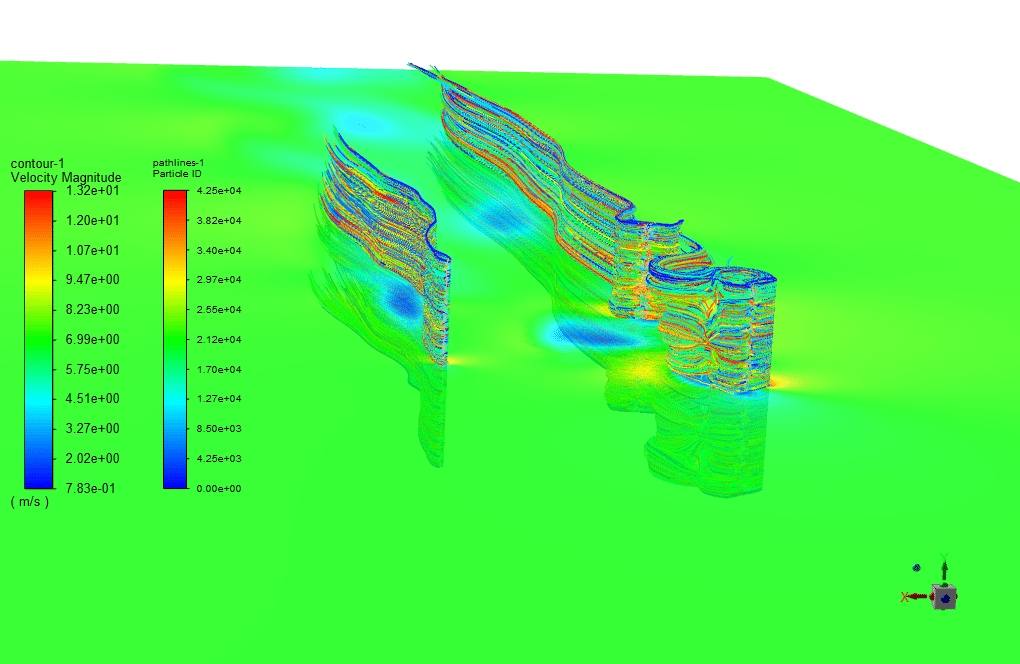
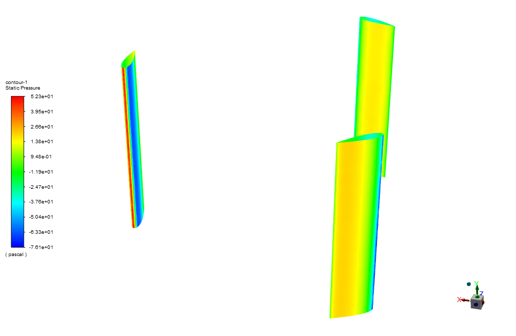
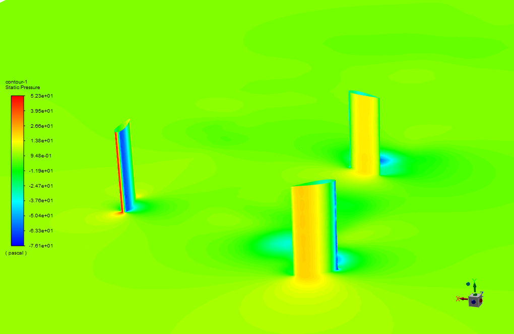
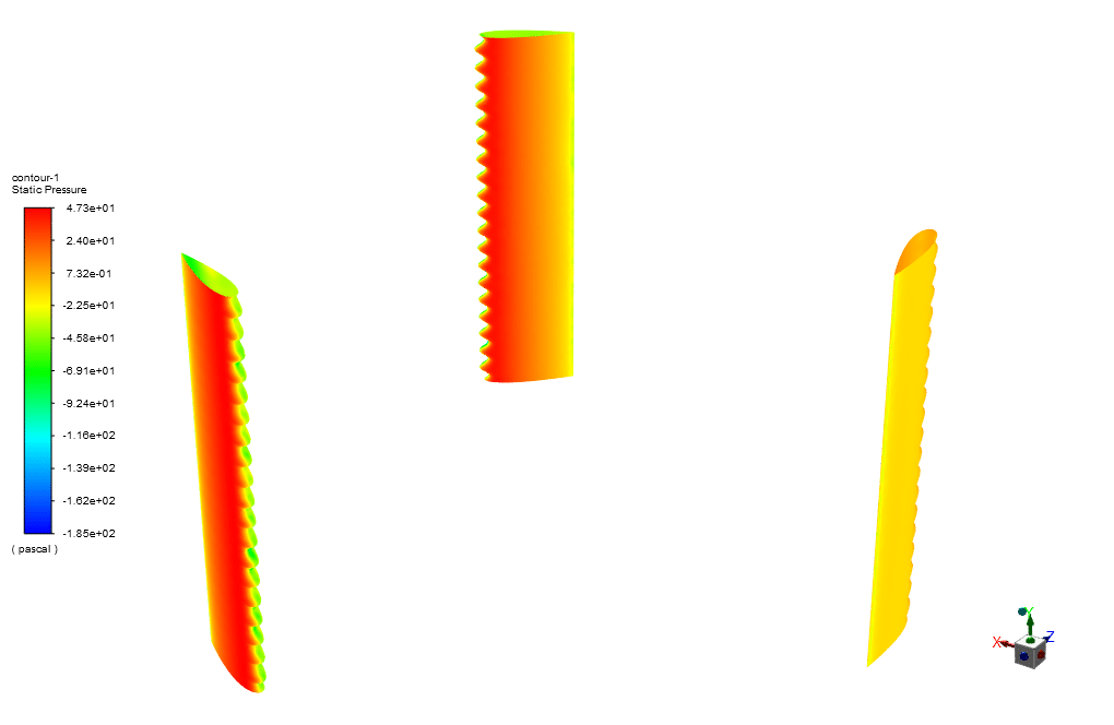
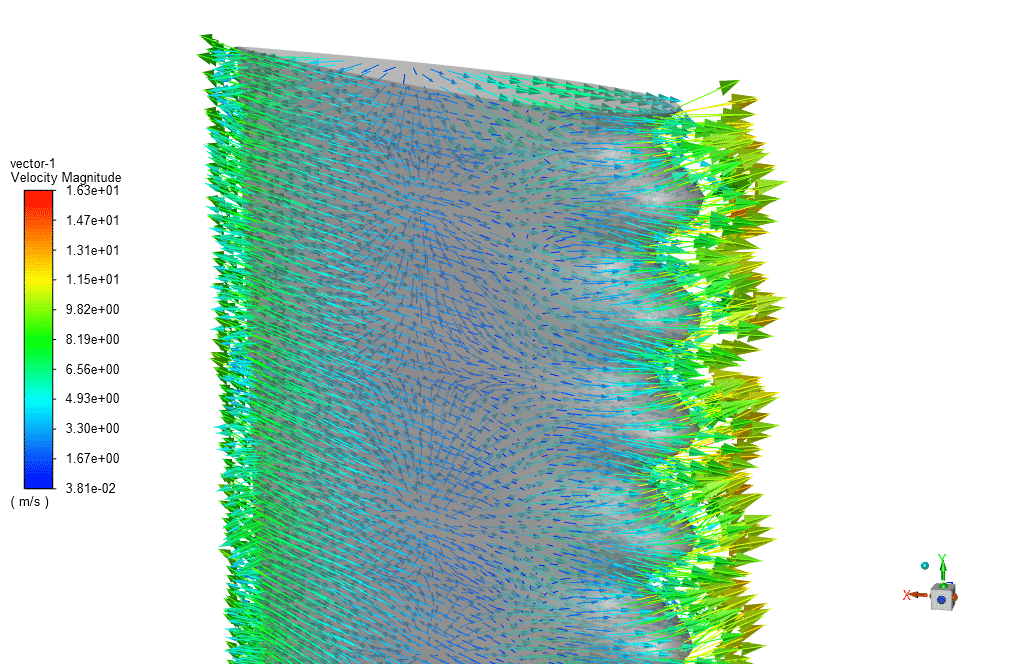
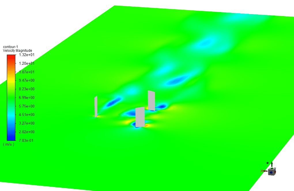
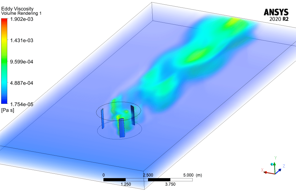
After the solution, two-dimensional contours related to the pressure, velocity, and streamlines are obtained.
For instance, as we can see in pressure contours, the pressure applied on the blades changes constantly due to constant variation of the position of the blades and, therefore, their angle of attack.
These constant changes in pressure bring up one of the significant challenges of VAWTs, which would be the dynamic stall. Also, due to changes in pressure, the blades of a VAWT are fatigue-prone due to the wide variation in applied forces during each rotation.
W can overcome these challenges by improving the design, including leading-edge serrated airfoils that can enhance the power and torque generated by these vertical axis turbines.
Next, if we investigate the changes in drag, lift, and power coefficient, we may observe a slight increase in drag force exerted on serrated airfoils compared to the plain ones, which seem to be due to the increased surface of the airfoils.
The following graph is related to the lift coefficient, showing a slight increase in the generated lift force when we use the serrated airfoils for the vertical axis turbine. The reason can be behind the more smoothed pressure distribution over two surfaces of a single airfoil.
In the serrated airfoils, the pressure gradient over two surfaces of each airfoil changes more smoothly compared to the plain airfoils causing the lift force to increase.
Finally, the generated power will slightly increase by improving the design, i.e., employing serrated airfoils. This phenomenon can be explained by the fact that the generated power is increased in each rotation cycle for each blade. This increase in power in each cycle will result in smoothed and increased power output.
The next two graphs delve more deeply into the details of power generation in each cycle and for each type of airfoils.
As was explained earlier, in the generated power coefficient graph, the smoothness of generated power for each airfoil is clearly shown.




Gino Kreiger II –
The serrated airfoil leads to smoother pressure distributions and increased lift force. Is this correlated with a significant improvement in energy efficiency compared to the plain airfoil, and if so, by how much?
MR CFD Support –
From the information provided, we can confirm that the serrated airfoil has an impact on the efficiency by smoothing the pressure distribution and increasing the lift force. However, the exact amount or percentage by which energy efficiency is improved is not specified. For precise effectiveness, quantifiable comparison data between serrated and plain airfoils power generation would be needed.
Ms. May Rath I –
After implementing the serrations on the airfoil, did the dynamic stall phenomenon decrease, and how significantly?
MR CFD Support –
The simulation projects and analyses that the serrations on the airfoil lead to the control and reduction of dynamic flow separation, which implies a mitigated dynamic stall phenomenon. Although specific quantitative results regarding the extent of this improvement are not provided here, serrated airfoils are generally observed to have more smoothed pressure distribution, leading to increased lift force and power generation, which is indicative of a less severe dynamic stall.
Ms. Karianne Simonis V –
The detail on the impact of serrated airfoils versus plain airfoils is valuable. Was the improvement in lift force due to the serrations significant enough to recommend their usage for all VAWT designs, or are there specific scenarios where they are more beneficial?
MR CFD Support –
The results showed a slight increase in lift force when using serrated airfoils, suggesting their potential benefits. However, recommending serrations for all VAWT designs would depend on various factors such as the application, environmental conditions, and cost-effectiveness analysis. It would be best applied to scenarios where dynamic stall and flow separation are significant performance challenges.
Jovany DuBuque III –
The comparison between the serrated and plain airfoil was thorough. I learned a lot about the challenges of the design and appreciated the detailed analysis. Thank you for explaining the benefits of the serrated design effectively.
MR CFD Support –
We’re grateful for your feedback! It’s fantastic to hear that the comparison provided valuable insights and that you appreciated the details of the analysis. If you need any further information or assistance with wind turbine simulations, feel free to reach out. Thanks for choosing our CFD Simulation Training.
Kameron Hills –
Are serrated airfoils always a better choice than plain airfoils for Darrieus wind turbines?
MR CFD Support –
The choice between serrated and plain airfoils for Darrieus wind turbines depends on specific design considerations and desired performance outcomes. Serrated airfoils may improve the lift force due to a smoother pressure distribution and can potentially increase generated power. They control and reduce dynamic flow separation, which is beneficial in the context of periodic dynamic stalls. However, they can also slightly increase drag force due to their increased surface area. The overall effectiveness of serrated airfoils should be assessed on a case-by-case basis, taking into account factors such as Reynolds number, operational conditions, and the specific turbine design.
Mercedes Zemlak –
Can this CFD analysis help in predicting the actual performance and efficiency of full-scale wind turbines in a real environment?
MR CFD Support –
Yes, this CFD analysis can provide valuable insights into the aerodynamic performance of wind turbines and predict how design changes – like the implementation of serrated airfoils – may impact efficiency. This can help inform design decisions before building full-scale models.
Marshall Lakin –
The article mentions using an RNG k-epsilon turbulence model for this CFD project. Can you explain why this particular turbulence model was chosen for comparing the performance of plain and serrated airfoils on the Darrieus VAWT?
MR CFD Support –
In the comparison of plain and serrated airfoils on the Darrieus VAWT, the RNG k-epsilon turbulence model was utilized due to its capability to handle flows involving rotation, boundary layers under adverse pressure gradients, and recirculation. This model is known for its improved accuracy over the standard k-epsilon model in predicting the complex aerodynamic phenomena associated with the dynamic stalling and flow separation encountered by the airfoils. It’s effective for capturing the effects of turbulence in rotating blades of the VAWT, which is critical for accurately predicting performance differences between plain and serrated blade designs.
Prof. Reggie Morissette –
This simulation sounds fascinating! Could you tell me if the increased power output for serrated airfoils is significant?
MR CFD Support –
The simulation shows a slight increase in the power output when employing serrated airfoils compared to the plain ones. Whilst the increase might not be drastically significant, the power curve smoothness and enhanced lift generated by the serrated airfoils are advantageous, indicating overall improved performance of the vertical axis wind turbines with this design modification.
Shyann Lynch –
This course made me confident in analyzing Darrieus wind turbines with both plain and serrated airfoils. However, I’m curious to know how significant the improvement is with serrated airfoils over plain ones in terms of power output?
MR CFD Support –
I’m glad to hear the course was helpful! Regarding the improvement, serrated airfoils typically exhibit a smoother pressure distribution that can slightly increase lift forces, which in turn can lead to an improvement in power output compared to plain airfoils. The increase in power is noticeable as it contributes to a smoother and consistent power generation for each blade in the rotation cycle, which results in an overall increased and stabilized power output for the turbine.
Lon Lynch –
The explanation is very thorough! Do the serrated airfoils also impact the noise level emitted from the VAWT?
MR CFD Support –
Yes, serrated airfoils can impact noise levels. Serrations can help in breaking up coherent vortex structures that contribute to noise generation, resulting in potentially quieter operation of the VAWT.
Prof. Talon Vandervort –
The improved power generation you mention in serrated airfoils is intriguing. Could you explain how the serration design actually helps in reducing the dynamic stall, and thus, in improving the overall performance of the turbine?
MR CFD Support –
The serration design on the leading-edge of the airfoils helps to mitigate the flow separation that occurs at the blade leading-edge during a dynamic stall. This is because the serrations act to break up coherent vortex structures that can form during rapid changes in angle of attack, leading to a delayed stall and smoother transition as the vortices break down. As the pressure distribution becomes smoother, the aerodynamic performance of the turbine improves, hence leading to an increase in the lift force and potentially reduced cycle-to-cycle torque variability. This means the turbine can operate more efficiently and reliably over a range of wind speeds.
Alaina Fisher –
I’m impressed with the depth of this comparison study! Could the serrations in the airfoil lead to issues like increased noise output, and has it been taken into account in this simulation?
MR CFD Support –
Thank you for your compliment! The focus of this CFD simulation study was to investigate the aerodynamic performance, such as drag, lift, and power coefficient improvements with serrated airfoil designs. Noise analysis is an equally important avenue of study but is not covered in depth for this specific simulation. Usually, separate acoustic simulations and analyses would be required to fully understand noise generation and propagation characteristics.
Miss Rubie Quigley MD –
Thank you for the fantastic overview and clear explanations of serrated versus plain airfoil systems for wind turbines. Do the results indicate any notable disadvantages of serrated airfoils, such as noise issues or maintenance challenges giv.
MR CFD Support –
Thank you so much for your review! We’re glad to hear that you found the content understandable and valuable. Regarding your question – in the report, we mainly focus on the improved performance and benefits of serrated airfoils, such as enhancing power and torque output. However, other aspects like potential noise or maintenance implications were not covered in detail. Typically, any structural modification to an airfoil can impact noise levels, and serrations may have their specific effects. Maintenance may be affected due to the more complex shape, but for thorough insights into these issues, dedicated studies or additional data are required. We appreciate your interest, and if you have further questions or need specific studies about these factors, do let us know!
Brennon Runolfsdottir –
Great insights from the analysis! However, what were the criteria for deciding the height and width dimensions of the computational domain in the project?
MR CFD Support –
In this specific CFD simulation, selecting an appropriate size for the computational domain is crucial to minimize boundary effects on the wind turbines while ensuring computational efficiency. The dimensions are chosen based on the turbine’s size, the expected flow field around it, and practical considerations like the computational resources available.
Norene Dach –
Is it normal to see an increase in drag for serrated airfoils in comparison to plain ones, and how does that affect overall turbine performance?
MR CFD Support –
Yes, it is normal to observe a slight increase in drag when serrated airfoils are employed, primarily due to the increased surface area from the serrations. This can lead to a slight trade-off in the performance because while serrated airfoils may generate more lift, the increased drag can slightly reduce the overall aerodynamics efficiency. However, these airfoils are designed to enhance lift significantly during dynamic stall conditions and smoother pressure distribution, which helps in overall power production for the turbine. Ultimately, the increase in power output that results from the smoothed pressure gradients and reduced flow separation can outweigh the negative effects of the increased drag, leading to improved turbine performance.
Wilfredo Bernier –
The training was immensely helpful. The comparison between serrated and plain airfoils in VAWTs implemented in the training gave me a profound understanding. Is it plausible to use these serrated airfoils on larger-scale wind turbines, or is the effect mostly significant at low Reynolds numbers as used in the simulations?
MR CFD Support –
The benefits of serrated airfoil designs can translate to larger-scale wind turbines. However, the larger the wind turbine, the more complex the aerodynamic interactions, and the higher the Reynolds numbers. Serrated airfoils may still improve the stall characteristics and overall aerodynamic performance but assessing their effectiveness at higher Reynolds numbers would require additional analysis to confirm applicability. The behavior might also vary significantly based on the specific design and operating conditions of the turbine.
Amina Murphy I –
I just finished the training on serrated vs plain airfoils, and the improvement in VAWT performance due to serrated airfoil design was fascinating. How did the serrated edges specifically help reduce the dynamic stall effect in these turbines?
MR CFD Support –
The serrations on the leading edge of the turbine blades help in delaying flow separation, thereby stabilizing the flow over the blade surface. This action reduces the large-scale vortex shedding that is characteristic of dynamic stall. Due to this effect, the severity and frequency of torque fluctuations are moderated leading to a more consistent and improved overall performance in the vertical axis wind turbines. The enhanced lift produced by the serrated design also contributes to this effect through improved aerodynamics.
Fritz Oberbrunner –
I was impressed with the clear comparison between serrated and plain airfoils in the simulation. Can the increased drag on serrated airfoils adversely affect the turbine’s performance over time?
MR CFD Support –
Indeed, the increased drag on serrated airfoils can lead to a higher aerodynamic resistance, which could potentially reduce rotational speed under certain conditions. However, the improved lift and smoother pressure distribution can compensate for drag, enhancing overall turbine efficiency. Durability and fatigue should be carefully considered in long-term performance analyses.
Prof. Marley Wiegand II –
After applying serrations to the airfoils in this project, is there any significant change in acoustics or noise level compared to the plain airfoil?
MR CFD Support –
In this CFD simulation, the focus has been on evaluating the aerodynamic performance of VAWTs with plain and serrated airfoils, specifically looking into pressure, velocity, lift, drag, and power coefficients. Acoustic analysis or noise level comparison between the plain and serrated airfoil configurations has not been mentioned as part of this study.
Wilma Stehr Jr. –
Afterreadingthisawesomeandveryinsightfulreview,Ijusthadaquickquestion:Has theEncapsulatedParticlemodelbeiinvestigatedasafunctionofserratedorplainedgesonflowdynamincs?Aremorefolksdoingresearchoriteffectonperformacnesincetheyrolateorcyclespeed?
MR CFD Support –
ThisreviewfocusesonthecomparisonofserratedandplainairfoilsinthecontextofaDarrieusVAWTratherthandirectlyaddressingtheuseofEncapsulatedParticlemodeloritseffectsonperformancesrelatedtocyclingorrotation.WithintheframeworkoftheexplainANSYSFluentsimulation,itdoesnotappearthattheEncapsulatedParticlemodewasinvestigatedfortheedgeconfiguration.
Graciela Hickle II –
What difference does serration make to the performance of the Darrieus wind turbines, compared to the plain airfoils?
MR CFD Support –
The serration on the leading edge of the turbine blades improves the power performance of the Darrieus wind turbines by controlling and reducing dynamic flow separation, which occurs at relatively low Reynolds numbers. This modification leads to reduced torque fluctuations, increases in lift force due to more smoothed pressure distribution, and ultimately a slight increase in overall power generated by these vertical axis turbines.
Hipolito Ortiz –
The comparison between plain and serrated airfoil effects on the dynamic stall phenomenon is very impressive. What particular benefits did the serrated airfoil provide in mitigating the dynamic stall compared to plain airfoils?
MR CFD Support –
The serrated airfoils help in smoothing the pressure distribution over the surfaces of the airfoil, which reduces the severity of dynamic stall by controlling and reducing dynamic flow separation. This leads to a smoother change in lift forces, a reduction in torque fluctuations, and an overall increase in power output for each rotation cycle of the VAWT blades.
Ms. Yvette Bartell –
I recently finished the serrated airfoil and plain airfoil comparison CFD simulation training using ANSYS Fluent, and it was truly insightful. The step-by-step approach to evaluating the dynamic stall phenomenon in VAWTs and exploring the efficiency gains with serrated airfoil designs was fascinating. It definitely added depth to my understanding of aerodynamics in wind energy applications.
MR CFD Support –
Thank you for your feedback! We’re thrilled to hear that you found the training insightful and that it deepened your understanding of wind turbine aerodynamics. At MR CFD, we always strive to provide detailed analyses that can help enhance the knowledge and skills of our users in practical CFD applications. We’re glad this training helped you in wind energy applications, and we appreciate you taking the time to share your experience.
Daniela Greenfelder –
This advanced simulation compared the H-type Darrieus wind turbines with plain and serrated airfoils. The introduction of leading-edge serrations seems like an innovative approach for enhancing the turbine’s performance. Is the slight increase in drag a concerning factor, or is it outweighed by the benefits in lift and power generation?
MR CFD Support –
The slight increase in drag experienced with serrated airfoils is not a major concern. While there is a small increase in drag force, the benefits in lift and power generation brought on by a more uniform pressure distribution across the airfoil surfaces far outweigh this minor cost. Serrations lead to better control of the dynamic flow separation, which enhances the overall performance of the wind turbine. Therefore, the use of serrated airfoils leads to an improvement in the net energy output of the VAWT despite the increased surface area that contributes to the drag.
Ashlynn Jakubowski –
Is the slight increase in drag force for serrated airfoils a concern when considering the overall efficiency of the turbine?
MR CFD Support –
The increased drag force is not necessarily a major concern. The serrated airfoil is designed to produce a smoother pressure distribution, which can increase lift and potentially improve the power output of the turbine. While drag does increase, the efficiency gains from increased lift and power can outweigh the negative impact of higher drag, enhancing the overall performance.
Osbaldo Muller –
Can serrated airfoils be actually used in real-life applications to enhance VAWT designs or are they just theoretical at this stage?
MR CFD Support –
Serrated airfoils are not just theoretical; they have practical potential for real-life applications. Their design modifications can address issues such as dynamic stall, and improving smoothness in pressure distribution can lead to real-world efficiency gains for vertical axis wind turbines.
Allan Orn III –
The simulation presents a practical comparison of plain and serrated airfoils in VAWTs. Could you explain the specific impact of the leading-edge serrations in improving the performance of airfoils during the dynamic stall?
MR CFD Support –
The leading-edge serrations help to smooth out the pressure distribution over the airfoil surfaces. During dynamic stall conditions, these serrations can delay flow separation, reducing torque fluctuations and enhancing lift. This results in more consistent performance and improved power output from the vertical axis wind turbine.
Anthony Ernser –
The analysis of serrated versus plain airfoils in the context of VAWTs was both fascinating and insightful. The juxtaposition of the pressure, velocity, and power generation between the two types of airfoils provided a deep understanding of the performance improvements achieved through minor adjustments in design. It’s incredible to see how the introduction of leading-edge serrations can mitigate the challenges associated with dynamic stall and enhance overall turbine efficiency. Complemented by illustrative graphs and a detailed account of the CFD process, this training material serves as a valuable resource for those interested in the aerodynamic optimization of wind turbines.
MR CFD Support –
Thank you for your review. We are thrilled to hear that you found the CFD simulation training for the serrated airfoil versus the plain airfoil to be enlightening and informative. Your understanding and appreciation of the detailed analysis presented encourage us to continue offering high-quality educational content. Thanks again for recognizing the value in our training materials!
Tamia Thompson –
The serrated airfoils seem to perform better according to the conclusions, but could you clarify if this improved performance comes at an increased manufacturing cost or any other operational drawbacks?
MR CFD Support –
Thank you for your insightful question! While the serrated airfoil design does produce a smoother pressure distribution, which can result in increased lift and overall power generation, there could be potential increases in manufacturing complexity and cost due to the intricate shape. Additionally, operational considerations might include potential for increased maintenance due to a higher surface area and more complex geometry. When evaluating such systems, a balance between performance improvements and the associated costs, both upfront and over the lifecycle of the turbine, must be considered.
Maddison Bins DVM –
Can you explain how the serrated airfoils improve the power output compared to plain airfoils?
MR CFD Support –
The serrated airfoils improve the power output by smoothing the pressure distribution over the airfoil surfaces, which increases the lift force. This enhancement in generated lift contributes to a more efficient power generation cycle, translating into a slight increase in power output for each rotation cycle of the turbine blades.