Twin Screw Pump, ANSYS Fluent CFD Simulation Training
$100.00 Student Discount
- The problem numerically simulates the Twin Screw Pump using ANSYS Fluent software.
- We design the 3-D model by the Design Modeler software.
- We Mesh the model by ANSYS Meshing software, and the element number equals 1184161.
- We perform this simulation as unsteady (Transient).
- We use the Mesh Motion method to define rotational motion around pump screws.
To Order Your Project or benefit from a CFD consultation, contact our experts via email ([email protected]), online support tab, or WhatsApp at +44 7443 197273.
There are some Free Products to check our service quality.
If you want the training video in another language instead of English, ask it via [email protected] after you buy the product.
Description
Description
This simulation is about a twin screw pump via ANSYS Fluent software. We perform this CFD project and investigate it by CFD analysis.
A twin-screw pump is a positive displacement pump, meaning that the pump transfers a particular volume of product according to the speed and pitch of the screws. While turning, the two screws form closed chambers that move in an axial direction.
This movement creates a vacuum at the inlet boundary and positive pressure at the outlet. Due to this double chamber technic, there is an almost pulsation-free working with high and low viscosity products.
In other words, screw pumps operate using two counter-rotating screw rotors engineered to rotate “towards each other.” This traps the gas in the space between the “screws” of their rotors. As the screws rotate, this trapped volume decreases, compressing the fluid and moving it towards the exhaust.
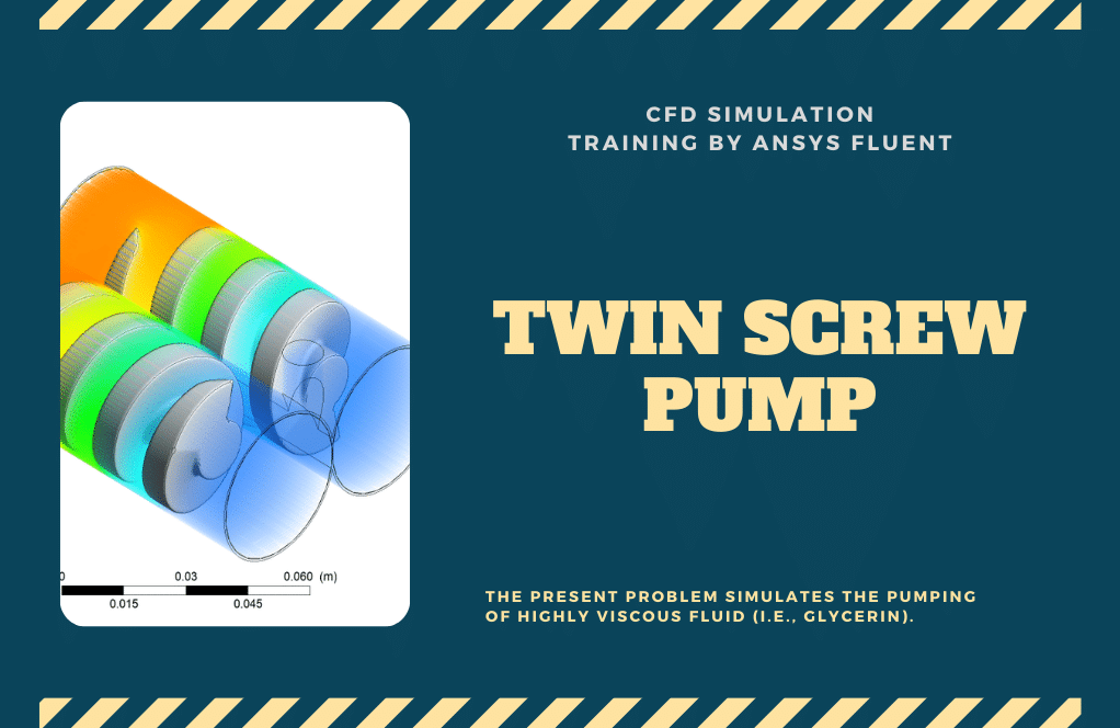
The present problem simulates the pumping of highly viscous fluid (i.e., Glycerin). In this project, the glycerin fluid is sucked inside the computational domain due to the rotation of screws. The twin-screw pump increases the pressure of the Glycerin and pushes it toward the outlet.
The geometry of this project was designed in Solidworks and then edited in ANSYS design modeler and contains two rotating zones and one stationary zone (pump crust).
The model is then meshed by ANSYS Meshing software. The model mesh is unstructured, and 1184161 cells have been created.
Twin Screw Pump Method
In this simulation, the rotational motion of the pump should be defined. Instead of the motion being applied to the pump rotor itself, it is applied to the surrounding fluid. So, a distinct computational zone is created in the cell zone conditions to define the rotational movement.
This work is done using the Mesh Motion method, and the rotational velocity of 3 rad/s is defined.
Also, at the inlet and outlet of the pump, a pressure boundary condition is used because the movement of the fluid inside the pump is not forced, and the fluid transfer occurs according to the pressure changes.
Twin Screw Pump Conclusion
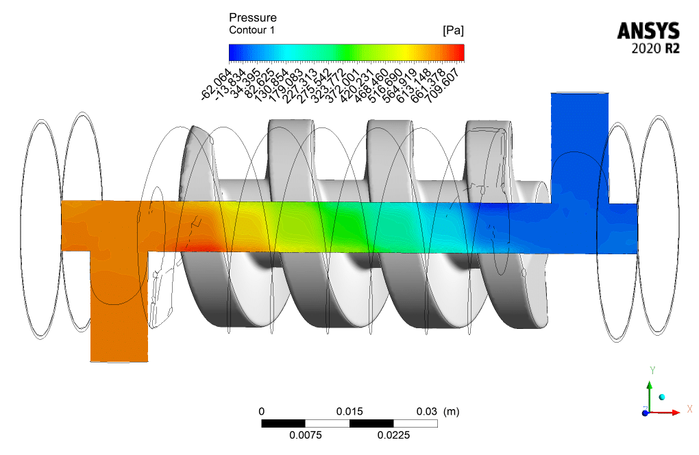
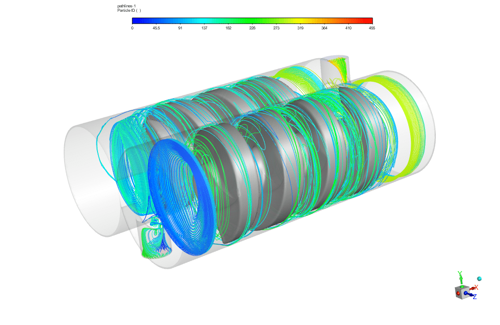
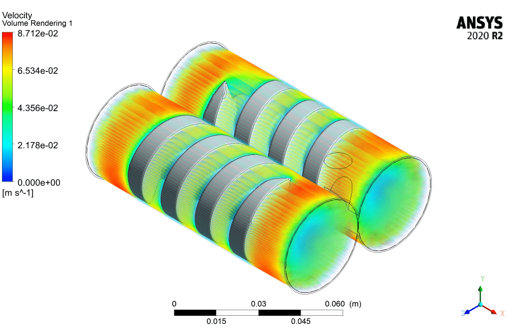
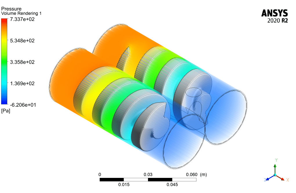
After simulation, 2D and 3D contours of velocity and pressure are obtained. Also, streamlines around the rotors are obtained. The results show that fluid flow is displaced by pressure.
The movement of the rotor causes suction pressure in the pump’s inlet and pushes it towards the outlet of the pump. Also, the flow lines show the rotational movement of the fluid inside the pump.



Harmony Legros –
The Twin Screw Pump simulation sounds fascinating! Can I utilize these results to model similar pumps for different fluids than glycerin?
MR CFD Support –
Absolutely! While this simulation is specific to glycerin, the results and methodologies can be applied to various other fluids. Adjustments may be needed to accommodate different fluid properties such as viscosity and density. Modify the simulation parameters accordingly and consult the CFD support for guidelines if needed.
Dereck Welch –
The twin screw pump simulation’s visual presentations of the flow were impressive—so much clarity. It helped me understand such a complex device!
MR CFD Support –
Thank you for your positive feedback! We are thrilled to hear that our visualizations in the twin screw pump simulation were helpful. Understanding complex machinery is fundamental, and it’s great to know our efforts are achieving that goal. If you have any more questions or need further assistance, please don’t hesitate to reach out.
Idella Greenholt IV –
I can see how the twin screw pump simulation helps understand the mechanics of the pump; very impressive detail!
MR CFD Support –
Thank you for your kind words! We’re thrilled to know that our twin screw pump simulation has provided you with a deeper understanding of the inner workings of the pump. It’s wonderful to hear that the level of detail in the simulation was impressive to you. Your satisfaction is our top priority, and we look forward to providing you with more high-quality learning products.
Eleanora Wilderman –
The simulation looks comprehensive, but I’m curious about how leakage between screws was prevented. Could you explain this part of the process?
MR CFD Support –
In the simulation of the twin screw pump, leakage prevention is a significant concern. To model the screws accurately, a high-quality mesh is generated to reduce the gap between the screws to a minimum. The clearance is typically set according to real-world specifications, and the simulation accounts for this minor gap, which should alleviate any significant leakage in the model. The fluid’s viscous properties and the screw’s precise geometric tolerance also help minimize the leakage between the screw gaps during the simulation.
Meggie Olson PhD –
I found the explanation for smooth, pulsation-free operation of the twin screw pump fascinating. The use of glycerin as the fluid to demonstrate the pump action provides a clear understanding of how high-viscosity fluids are handled. Excellent training resource!
MR CFD Support –
Thank you for your positive feedback! We’re glad that the simulation gave you a clear understanding of how twin screw pumps operate, especially with high-viscosity fluids like glycerin. We appreciate you taking the time to review our training material and are happy to hear that you found it an excellent resource for learning.
Darrion Reynolds –
The twin screw pump simulation is thoroughly explained and seems to rigorously demonstrate the flow phenomena within the pump. The use of glycerin, a highly viscous fluid, shows the versatility of the pump simulation for different industries, whether it’s food, cosmetics, or any other industry where handling such fluids is common. The detailed approach to create distinct computational zones and the incorporation of pressure boundary conditions provide insight into how CFD tools mimic complex machinery. Understanding how the fluid is displaced and the rotational effects on the flow is key to maximizing efficiency and preventing potential issues in the pump’s real-world application. Congratulations on the successful simulation!
MR CFD Support –
Thank you for the positive feedback! We’re delighted to hear that our simulation could effectively showcase the versatile capabilities of a twin screw pump and that the explanations were clear and useful to you. It’s great to know our simulation training helped in understanding the complexities of screw pump operation and actual flow movement within such devices. We always strive to deliver comprehensive and applicable CFD learning materials, and hearing that our efforts translate into greater knowledge for our customers is truly rewarding. We appreciate your commendations and look forward to providing more insightful simulations for you in the future!