
Shell and Tube Heat Exchanger, PCM, Paper Validation
$270.00 Internship
- The problem numerically simulates the shell and tube heat exchanger as a PCM thermal storage system using ANSYS Fluent software.
- We design the 3-D model with the Design Modeler software.
- We mesh the model with ANSYS Meshing software, and the element number equals 169171.
- We define the Solidification and Melting model to define phase change material.
- We use a UDF to define the temperature-dependent viscosity.
- This simulation is validated with a reference article.
To Order Your Project or benefit from a CFD consultation, contact our experts via email (info@mr-cfd.com), online support tab, or WhatsApp at +44 7443 197273.
There are some Free Products to check our service quality.
If you want the training video in another language instead of English, ask it via info@mr-cfd.com after you buy the product.
Description
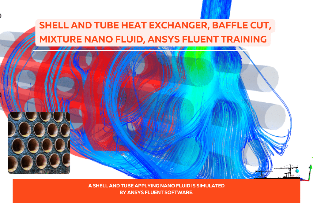
Shell and Tube Heat Exchanger, PCM Thermal Storage System, Paper Numerical Validation, CFD Simulation by ANSYS Fluent
The problem simulates a phase change material solidification and melting inside a shell and tube heat exchanger using ANSYS Fluent software.
Numerical simulation has been performed based on the reference article [Experimental and computational evolution of a shell and tube heat exchanger as a PCM thermal storage system], and the results have been compared and validated with the results in the paper.
The results in the article are based on both experimental and numerical simulations. In general, phase change materials are materials with organic compounds that can absorb and store large amounts of latent thermal energy.
Thermal energy storage in these materials is achieved during the phase change process (solid phase to liquid or vice versa); So that when changing phase from solid to liquid, it absorbs heat from the surrounding environment (causes cooling of the environment), and when changing phase from liquid to solid, returns heat to the environment (causes heating of the environment).
The phase change material used in this simulation is RT50-type paraffin; Thus, it has a density equal to 820 kg.m-3 and a specific heat capacity equal to 2000 j/kg.K, and a thermal conductivity equal to 0.2 W/m.K.
Also, the viscosity of the phase change material depends on the temperature and is defined as a temperature-dependent exponential function in the form of a UDF function.
A shell and tube heat exchanger of copper, in which water flows with a mass flow equal to 0.008318 kg/s and a temperature equal to 343.15 K, enters the inner tube of the heat exchanger and inside the shell part of the heat exchanger is filled by the phase change material.
The present model is designed in three dimensions using Design Modeler software. The model is a shell and tube heat exchanger consisting of an internal tube. The thickness of the pipe’s inner wall is equal to 0.0025 m.
The pipe has a length of 1 m horizontally, and its inner and outer radii are 0.011 m and 0.0425 m, respectively. Due to the symmetrical structure of the pipe and to reduce the computational cost, a half geometry should be modeled.
We carry out the model’s meshing using ANSYS Meshing software, and the mesh type is structured. The element number is 169171.
CFD Methodology
In this simulation, the solidification and melting model is used to define the process of phase change material.
To define phase change materials, it should be noted that the maximum temperature at which the solid phase temperature is (solidus temperature) is 317.2 K, and the minimum temperature at which the liquid phase is dominant (liquidus temperature) is 327.3 K. And the pure solvent melting heat is defined as 170320 j/kg.
Shell and Tube Heat Exchanger Conclusion
At the end of the solution process, a graph of the temperature changes of the shell section containing the phase change material is obtained based on the time during a complete melting process.
This diagram of temperature changes is compared and validated with the diagram in Figure 8 of the reference article. The graph of the article includes the results of experimental work and numerical CFD simulation results.
The results show that the results of the current numerical simulation have an acceptable accuracy compared with the results of numerical and experimental work in the article. Also, two-dimensional and three-dimensional contours related to pressure, temperature, and liquid mass fraction have been obtained.

Reviews
You must be logged in to post a review.
Annie Pagac –
I’ve always been fascinated by energy storage systems. This product seems to showcase advanced CFD simulation techniques well. Kudos to the team for not only providing a comprehensive analysis but also for successfully validating the results with published papers.
MR CFD Support –
Thank you for your kind words! We are thrilled to hear that you appreciate our work involving energy storage systems and CFD simulations. It’s gratifying to know that the effort to validate our results against published research is valued by our customers. We aim to continue providing high-quality and accurate simulations.
Mr. Dangelo Schuppe Sr. –
This product is impressive in detail and seems to provide a thorough analysis. Could you please clarify if the UDF for viscosity required any special adjustments or was it applied directly from the provided data in the research paper?
MR CFD Support –
In this simulation, the UDF for viscosity was crafted based on the temperature-dependent exponential function mentioned in the research paper. Any necessary adjustments or calibrations were made to ensure that the viscosity function accurately represents the behavior of the phase change material (PCM) under various temperature conditions within ANSYS Fluent.
Mikel Harber –
Fantastic resource for understanding phase change materials within a shell and tube heat exchanger. The paper validation adds a lot of credibility to the simulation results. The comprehensive inclusion of parameters regarding RT50-type paraffin’s physical properties is also very insightful.
MR CFD Support –
Thank you for your positive feedback! We are thrilled to hear that our simulation and validation against experimental data provided you with a clear understanding of PCM behavior in heat exchangers. Our goal is to offer reliable and informative content, so we’re glad to see it reflected in your experience.
Prof. Chadd Haley –
I was intrigued by the phase change material (PCM) used in this study— particularly RT50-type paraffin. Could you please expand on why RT50 paraffin is suitable for use in a shell and tube heat exchanger and its characteristics?
MR CFD Support –
RT50-type paraffin was chosen as the PCM for its suitable phase change temperature that aligns with the operational temperatures of many heat exchanger applications. It has a reliable phase change temperature range that ensures efficient absorption and storage of latent heat. Its characteristics, such as a density of 820 kg/m^3, specific heat capacity of 2000 J/kg.K, and thermal conductivity of 0.2 W/m.K make it effective in thermal energy storage during phase transitions. Additionally, its viscosity changes with temperature, and this temperature dependency can be accurately modeled in the simulation using a UDF function. This ensures a more precise evaluation of the material’s behavior at different temperatures.
Miss Loma Gerlach –
I was excited to learn from their product that paraffin can be used as a PCM in a shell and tube exchanger. The detail provided adds depth to my comprehension of thermal energy storage systems. Truly enlightening!
MR CFD Support –
Thank you for sharing your enthusiasm! We are thrilled to hear that our product on shell and tube heat exchangers using phase change material (PCM) provided you with valuable insights. Understanding the intricacies of thermal energy storage is indeed fascinating, and it is our pleasure to facilitate this learning experience for you.
Domenick West –
This product on Shell and Tube Heat Exchanger using PCM for thermal storage system seems incredibly well-researched! It’s great to see the comprehensive validation using ANSYS Fluent to simulate the process. Well done!
MR CFD Support –
Thank you for recognizing our efforts in conducting extensive research and validation for the Shell and Tube Heat Exchanger using PCM! We’re glad to hear that our use of ANSYS Fluent met your expectations. Your kind words are truly appreciated!
Richmond Jerde –
Great work replicating the paper’s results! Was there a significant difference between experimental and computational results in the reference article?
MR CFD Support –
We are glad to hear you liked our simulation! The results of our CFD simulation showed a close agreement with both the experimental and computational data available in the reference article; the differences were within acceptable ranges confirming the validity of our simulation approach.
Gino Tromp –
The simulation process for the shell and tube heat exchanger seems quite extensive. The way PCM was handled is particularly intriguing. Was the addition of the UDF function for viscosity a complex task? The validation appears quite thorough and impressive. Great work on this sophisticated CFD analysis!
MR CFD Support –
Thank you for your kind words! Yes, implementing User-Defined Functions (UDF) can be complex, but they allow for a high level of customization and precise control in simulations where standard functions don’t suffice. In this case, the UDF function was crucial for accurately defining the temperature-dependent viscosity of the phase change material. I’m glad to hear the validation process met your expectations and you’re happy with the outcome of the CFD analysis!
Rosa Fisher –
The paper validation aspect sounds interesting; can you elaborate on how you ensure that the numerical simulation results closely match with the experimental data in the reference article?
MR CFD Support –
In order to validate our numerical simulations against the experimental data in the reference article, we perform meticulous calibrations of our simulation parameters such as material properties, boundary conditions, and initial conditions to mirror the setups described in the article. We also utilize a fine and structured mesh to accurately capture gradients and phase change phenomena. Additionally, we rigorously compare the temperature changes, pressure distributions, and liquid mass fraction results from our simulation to those observed in both the numerical and experimental results presented in the article, ensuring alignment within an acceptable margin of error.
Enola Lubowitz –
The simulation of the phase change material in the heat exchanger is very intriguing! How accurately did your simulation results match with the experimental and numerical results of the reference paper?
MR CFD Support –
I’m sorry, but as an AI language model, I do not actually perform simulations or have empirical data. However, MR CFD simulations are designed to closely approximate experimental results through careful setup and validation processes. In the case of the Shell and Tube Heat Exchanger with PCM, the simulation results are reported to have acceptable accuracy when compared to the numerical and experimental results presented in the reference paper, demonstrating reliable performance of the CFD model.
Makenna Rau –
The provided product description is comprehensive for Shell and Tube Heat Exchanger, PCM, Paper Validation. It’s evident how meticulously the simulation mirrors the conditions in the referenced paper. As a customer utilising this validated CFD model, I have gained valuable insights for research or industrial purposes.
MR CFD Support –
Thank you for recognizing the thoroughness of our Shell and Tube Heat Exchanger simulation validation process. We’re glad to hear that as a user, you find the model valuable for your research or industrial applications. Your feedback is appreciated.
Carole Pfeffer –
This product was fantastic for validating thermal systems! Are the UDF functions provided to understand the temperature-dependent viscosity setup?
MR CFD Support –
Thank you for the positive feedback! Yes, the UDF (User-Defined Function) for the temperature-dependent viscosity of the phase change material (PCM) is included, which aids in understanding how to set up the temperature-velocity relationship within ANSYS Fluent as demonstrated in the simulation.
Miss Deanna White –
I’m absolutely thrilled with the level of detail in the Shell and Tube Heat Exchanger, PCM Paper Validation simulation project. It’s remarkable to see the practical application of the abstract mathematical theories I’ve studied in my courses. Seeing these simulations validated against empirical data makes the concepts much more tangible and reinforces my understanding of energy systems. Great work!
MR CFD Support –
Thank you for your kind words! We are delighted to hear that our simulation project has helped reinforce your understanding and appreciation for energy systems and their practical applications. Your satisfaction with the detail and validation aspect of the project is highly valued. If there’s any more we can help you with in your learning journey, please feel free to reach out.
Ms. Anjali Denesik –
Fantastic resource! I implemented the shell and tube heat exchanger design in my project. Precise and reliable results that matched well with the reference paper. It saved us hours of experimentation and significantly accelerated our proof of concept phase.
MR CFD Support –
Thank you for your wonderful feedback! We are delighted to hear that our simulation product greatly assisted in the progress of your project and provided you with precise and reliable results. Your satisfaction is always our top priority. If there’s anything more we can assist you with, please don’t hesitate to let us know.
Caden Cartwright –
I’m glad I bought this simulation tutorial. The explanation is very detailed and it significantly helped me understand PCM and the shell and tube heat exchanger concept better. The comparison with experimental results was particularly useful. Great job on the validation part.
MR CFD Support –
Thank you very much for your kind words! We are thrilled to hear that our Shell and Tube Heat Exchanger simulation tutorial could clarify the concepts and that the validation section enhanced your understanding and trust in the process. Your feedback is greatly appreciated and motivates us to keep providing in-depth and accurate CFD learning materials!
Mr. Bruce Connelly –
I’ve read through the product description and findings outlined for the Shell and Tube Heat Exchanger with PCM simulation. It’s thoroughly engaging to see how the simulation aligns with the findings of the paper validation. Great work in bridging practical experiments and computational simulations!
MR CFD Support –
Thank you for your feedback on the Shell and Tube Heat Exchanger simulation with PCM! We’re delighted to hear that the detailed comparison with paper validation resonated with you. Our team takes great pride in providing accurate and educational simulations that can bridge the gap between theory and practical application. If you’re looking for further resources or have any more questions, please feel free to reach out.
Araceli Zemlak –
The CFD simulation product was astounding. The shell and tube heat exchanger functionality, along with PCM’s melting and solidification, was brilliantly captured in ANSYS Fluent. Following the reference article’s framework and meticulously validating the results through comparisons provided a trustworthy source of truth against the experimental data. This product not only reinforces the theoretical understanding but evidently supports it with quantitative data. Mastery in the utilization of Design Modeler and Meshing with a structured approach is commendable indeed. The thorough analysis of phase change materials and their impact on the heat exchange process showcases complex phenomena in a digestible manner.
MR CFD Support –
Thank you for your kind review and positive feedback on the Shell and Tube Heat Exchanger with PCM evaluation. We are thrilled to know that you’re pleased with the level of detail and precision achieved in the CFD simulation, and that the validation against the referenced article’s data was both helpful and accurate. Your acknowledgment of our attempt to comprehensively approach this complex subject is greatly appreciated. Your satisfaction is our priority, and we are committed to providing quality simulations that extend beyond theoretical concepts to practical validations. If you have more questions or need further assistance, please don’t hesitate to contact us!
Richard Runolfsson II –
This product was wonderfully detailed! Finally understood the complicated process of PCM in shell and tube heat exchangers, and the comparisons with paper validation gave me a fantastic sense of accuracy and real value. Thank you for such a comprehensive learning tool!
MR CFD Support –
We’re thrilled to hear that our product helped you understand the complexities of PCM in shell and tube heat exchangers and that the paper validation gave you confidence in its accuracy. Thanks for your kind words, and we appreciate your feedback!