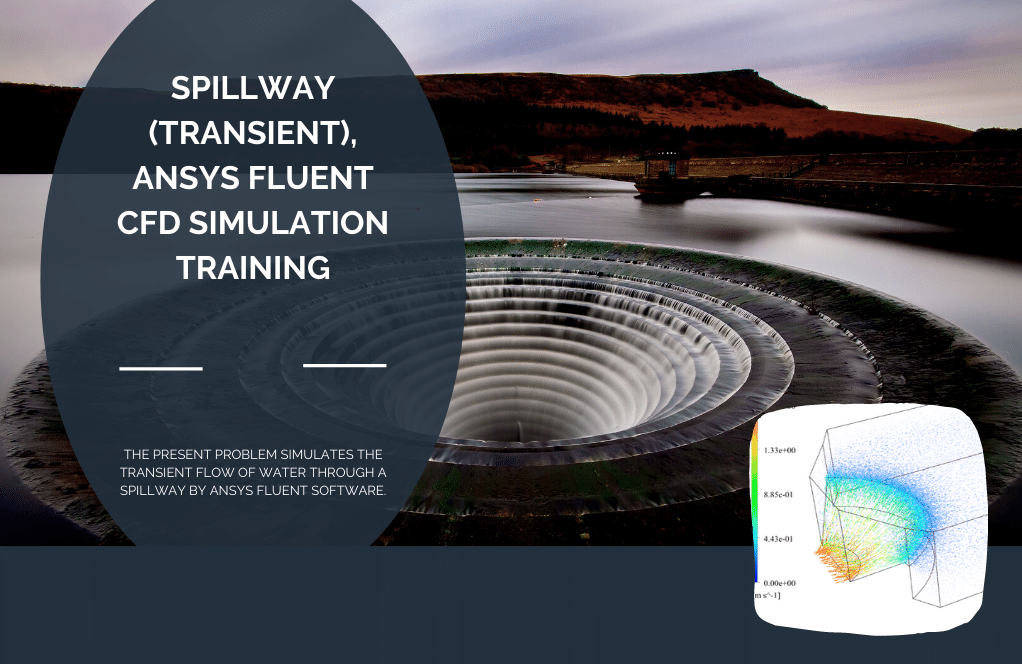
 Cfd Simulation, Ansys Fluent Training 1")
Stepped Spillway (Stair Spillway) CFD Simulation, ANSYS Fluent Training
$100.00 Internship
In this analysis, two-dimensional simulation of a stepped spillway by ANSYS Fluent software is presented.
Click on Add To Cart and obtain the Geometry file, Mesh file, and a Comprehensive ANSYS Fluent Training Video.To Order Your Project or benefit from a CFD consultation, contact our experts via email (info@mr-cfd.com), online support tab, or WhatsApp at +44 7443 197273.
There are some Free Products to check our service quality.
If you want the training video in another language instead of English, ask it via info@mr-cfd.com after you buy the product.
Description
Stepped Spillway Introduction
Stepped spillway is commonly used in reservoir dams in order to release flood safely. The stairs of spillway increase energy dissipation greatly. Stair spillways are among the hydraulic structures which attracted great interest to the designers due to their high water capacity energy dissipation. The flow mechanism is complicated in such structures, and more research is being done about it. For this reason, more research and simulation are needed to understand the fluid flow pattern correctly.
Stair Spillway Project description
In this analysis, two-dimensional simulation of a stepped spillway by ANSYS Fluent software is presented. VOF model is activated for two phases of air and water and standard k-e model with the use of standard wall function is exploited for fluid flow analysis.
Stepped Spillway Geometry & Mesh
The modeled geometry is designed and meshed inside Gambit®. The mesh type used for this geometry is unstructured and the element number is 139067.
 Cfd Simulation, Ansys Fluent Training 7")
 Cfd Simulation, Ansys Fluent Training 8")
CFD Simulation Settings
The key assumptions considered in this project are:
- Simulation is done using pressure-based solver.
- The present simulation and its results are considered to be steady and do not change as a function time.
- The effect of gravity has been taken into account and is equal to -9.8 m/s2 in Y direction.
The applied settings are summarized in the following table.
| (stepped spillway) | Models | |
| Viscous model | k-epsilon | |
| k-epsilon model | standard | |
| near wall treatment | standard wall function | |
| Multi phase | VOF | |
| Phase 1 | Air | |
| Phase 2 | Water | |
| (stepped spillway) | Boundary conditions | |
| Inlets | velocity inlet | |
|
Water inlet |
velocity | 1 m/s |
| Turbulent kinetic energy | 1 m2/s2 | |
| Turbulent dissipation rate | 1 m2/s3 | |
| Outlets | Pressure outlet | |
| Walls | ||
| wall motion | stationary wall | |
| (stepped spillway) | Solution Methods | |
| Pressure-velocity coupling | Simple | |
| Spatial discretization | pressure | PRESTO! |
| Volume fraction | first order upwind | |
| momentum | first order upwind | |
| turbulent kinetic energy | first order upwind | |
| turbulent dissipation rate | first order upwind | |
| (stepped spillway) | Initialization | |
| Initialization method | Standard | |
| gauge pressure | 0 Pa | |
| velocity (x,y,z) | (1,0,0) m/s | |
| Turbulent kinetic energy | 0 m2/s2 | |
| Turbulent dissipation rate | 1 m2/s3 | |
| Water volume fraction | 0 | |
Results
The contours of pressure, velocity, volume fraction, streamlines and velocity vectors are presented.
Reviews
You must be logged in to post a review.
Miss Jada Kozey –
This simulation is a fantastic tool for understanding the complex behavior of conical solar collectors!
Kenton Shields –
Can this simulation be used to optimize the design of stepped spillways
MR CFD Support –
Sure! The insights gained from this simulation can be instrumental in optimizing the design of stepped spillways, improving their efficiency and safety.
Eldred Mueller –
What types of boundary conditions are implemented in this simulation?
MR CFD Support –
The simulation employs velocity inlet and pressure outlet boundary conditions, accurately representing the flow conditions over a stepped spillway.
Marley Franecki –
I was fascinated by your detailed explanation of the Stepped Spillway simulation. Impressive how the stairs increase energy dissipation and improve safety during floods. Seeing the flow mechanisms create interest for more research, and simulations like this are crucial. Your application of the VOF model and standard k-e turbulence modelling surely demonstrates technical expertise!
MR CFD Support –
Thank you for the positive feedback! We are delighted to hear you appreciated the depth and detail of our Stepped Spillway CFD Simulation training. It is our aim to provide insightful and comprehensive learning resources that can enhance understanding and expertise in fluid dynamics and engineering. We take pride in our work and are always glad when our efforts resonate with our customers. If ever you have questions or need further assistance, we’re here to help!
Abdiel Reichert –
The training material was quite detailed and comprehensive. The utilization of the pressure-based solver and the specific settings for the simulation, including the gravity value and initialization parameters, seem particularly well-thought. Additionally, the presentation of results with pressure and velocity contours, among other details, seems like a valuable component of this training which can greatly help in understanding the complexities involved in stepped spillway simulations.
MR CFD Support –
Thank you for your thoughtful feedback. We’re thrilled to hear that the details and complexities of the Stepped Spillway simulation were presented clearly and usefully in the training material. Your appreciation motivates us to continue providing high-quality CFD training sessions. We’re here to support any continued learning and simulation endeavors you have!
Dr. Merlin Gottlieb V –
I recently completed the Stepped Spillway CFD Simulation course from MR CFD Company using ANSYS Fluent and I’m thrilled with what I’ve learned. The detailed treatment of the energy dissipation and the use of the VOF model helped me understand this hydraulic structure’s dynamics much better. The structured lessons and clear explanations of Gambit® meshing made the complex analysis manageable. I appreciate the thoughtful representation of results, like pressure contours and streamlines that give a clear visual understanding of the fluid flow
MR CFD Support –
Thank you so much for the positive feedback! We’re delighted to hear that our course on Stepped Spillway CFD Simulation was beneficial to you and provided clarity on the subject. We aim to provide comprehensive training that enables our students to fully grasp complex concepts and apply them effectively. Your compliments on our structured lessons and use of visual aids are very much appreciated. It’s rewarding to know you’ve gained valuable insights from our course. Keep exploring and learning with us!
Miss Minnie Lockman II –
The ANSYS Fluent simulation of a Stepped Spillway is truly impressive. The detailed methodology gives clear insights into hydration dynamics while ensuring high energy dissipation. It’s fascinating to see how the VOF model and standard k-epsilon turbulence approach are combined to yield such precise results. Great job on capturing the complexity of the flow mechanism!
MR CFD Support –
Thank you for your positive review! We’re glad to know that our training for the stepped spillway simulation with ANSYS Fluent met your expectations and that you found the use of the VOF model and k-epsilon turbulence model detailed and informative. It’s rewarding to see our customers appreciate the effort and precision put into these simulations.
Leopold Koelpin Jr. –
This ANSYS Fluent training for the stepped spillway simulation is so well-explained! Everything from the stair spillway geometry to the detailed settings for the CFD simulation is meticulously detailed. I particularly liked the use of the standard k-epsilon model for fluid flow analysis and how gravity was incorporated. The resulting pressure and velocity contours, as well as the streamlines, really help in understanding the complex flow patterns over the stairs. Great work on designing a thorough training module!
MR CFD Support –
Thank you so much for your positive feedback! We’re glad to hear that the simulation explanation and the comprehensiveness of the training module met your expectations. It’s our aim to ensure that complex flow patterns are clearly understood through the effective presentation of simulation results. We look forward to providing you with more quality training materials!
Timothy Block –
Great course! The step-by-step approach and detailed settings clearly explained how to set up and run a stepped spillway simulation. The visuals in the results made understanding the fluid dynamics so much easier.
MR CFD Support –
Thank you for your positive feedback! We’re delighted to hear that you found the course on stepped spillway simulation comprehensive and helpful, especially the focus on visualizing the fluid dynamics. If you have any further questions or need more clarifications, we’re always here to assist you.
Mrs. Karlee Friesen –
The simulation from MR CFD helped me grasp how stepped spillways function and the crucial role they play in energy dissipation. Visualizing the flow with the given parameters made the concept much clearer. Thank you for a high-caliber learning experience.
MR CFD Support –
We’re delighted to hear that our simulation on stepped spillways provided you with valuable insights into hydraulic structures and helped clarify the concepts involved. Thank you for choosing our ANSYS Fluent training—you validate our commitment to creating top-quality educational content. If there’s anything else we can assist you with in your CFD learning journey, don’t hesitate to reach out. Your success is our top priority!
Dr. Mireille Larson –
This stepped spillway simulation helped me gain a comprehensive understanding of flow patterns on a stair spillway. It was remarkable how the turbulence was effectively showcased. Could this simulation be used for educational purposes, such as lectures or demonstrations in fluid mechanics classes?
MR CFD Support –
Absolutely, the simulation we provide is a great resource for educational purposes. It offers insight into the complex mechanisms of flow over a stepped spillway and can certainly be utilized to enhance the learning experience in fluid mechanics courses. Teachers and students alike can benefit from the visual demonstrations and analytical data provided by such a detailed CFD simulation.
Dora Kilback –
I was impressed with how the Stepped Spillway CFD simulation accurately models the flow of water. The detailed visualization of pressure, velocity, and energy dissipation brings clarity to design considerations for hydraulic structures.
MR CFD Support –
Thank you for the positive feedback! We are thrilled to hear that the clarity and detailed visualization of our Stepped Spillway CFD simulation has been helpful. It’s great to know that our efforts in providing accurate and insightful models are appreciated.
Sigmund Waters –
I’ve learned a lot about stepped spillways from your CFD simulation training on ANSYS Fluent. The detailed explanation of the flow mechanics on such structures was incredibly insightful, and the use of the VOF and standard extit{k}- extit{ε} models made the complex topics easier to comprehend. Good job on choosing an unstructured mesh to capture the intricate flow details on the stairs!
MR CFD Support –
Thank you for taking the time to review our training on Stepped Spillway CFD Simulation using ANSYS Fluent. We’re very pleased to hear that you found the materials insightful and that the simulation setup contributed to a deeper understanding of the flow dynamics in stair spillways. Your input is valuable, and it encourages us to continue producing quality learning materials.
Darren Larson –
I’m amazed by the qualification of the analysis! Could you tell me more about how the VOF (Volume of Fluid) model benefits this type of CFD simulation?
MR CFD Support –
In this CFD simulation, the VOF model is employed to track the interface between air and water, which is crucial for capturing the complex free-surface flow over the stepped spillway. It’s highly effective for multiphase simulations where fluid motion is influenced by surface tension and gravity, as it can handle the discontinuities at the phase boundaries very well.
Mr. Leone Vandervort IV –
I found that the Stepped Spillway CFD simulation training was highly instructive. As someone interested in hydraulic structure design, the detailed approach to simulating water flow and energy dissipation over the spillway steps enhanced my understanding. The clear delineation of settings and boundary conditions in the tutorial provided a structured learning experience. Great work!
MR CFD Support –
Thank you for your review! We’re glad the training was helpful and provided you with valuable insights into hydraulic structure simulation. We strive to deliver clear and comprehensive learning materials, and your feedback is important to us. Keep an eye on our upcoming products for more informative content!
Heath Considine –
This simulation is a groundbreaking development in the field of hydraulic engineering and water resources management!
Xzavier Carroll –
I have always been fascinated by step spillways in dam engineering. The increased energy dissipation cited in this CFD simulation sounds impressive. Can we deduce from this analysis if this spillway design is more efficient compared to flat-sloped spillways?
MR CFD Support –
Yes, the CFD analysis of a stepped spillway can show a marked improvement in energy dissipation effectiveness compared to flat-sloped spillways. The simulation uses the Volume of Fluid (VOF) method and standard k-epsilon models to provide detailed insights into the fluid flow pattern and energy dissipation across the steps.
Brain Lowe –
The Stepped Spillway simulation was fantastic. Seeing how the VOF model managed the air-water interaction and how the energy dissipation increased due to the stepped configuration was enlightening.
MR CFD Support –
Thank you for your compliments! We’re glad to hear the simulation on the Stepped Spillway provided valuable insights into how the VOF model works and the effects of the stair configuration on energy dissipation. It’s great to know that our training product met your expectations and you found it enlightening.
Anthony Ullrich –
I had a great experience using MR CFD’s Stepped Spillway simulation training. The detailed guidance through complex fluid patterns was extremely helpful. The use of the VOF model and k-e turbulence approach was particularly insightful for capturing the water and air phases, which really helped me to understand the dynamics of stepped spillways better.
MR CFD Support –
Thank you for your positive feedback on the Stepped Spillway simulation training. We’re delighted to hear that our product helped you gain a better understanding of spillway dynamics and fluid patterns. Your satisfaction is paramount to us, and we always strive to deliver comprehensive and insightful CFD training modules. If you have further questions or need additional assistance, please don’t hesitate to reach out!
Kianna Barrows –
I’ve studied your spillway simulation, and the details are impressive! The use of the VOF model and the standard wall function really captures the complexities of spillway flow. Your approach takes energy dissipation into account effectively through your design choices. I particularly appreciate the visualizations – seeing the pressure and velocity contours helps a lot in understanding the interplay between water and structure.
MR CFD Support –
Thank you for your positive feedback! We are delighted to hear that you are impressed with the results and visualizations provided in our simulation model. Our aim is to represent the complexities as accurately as possible and help users get a better understanding of flow dynamics in such hydraulic structures. Your appreciation really encourages us to continue delivering high-quality simulations and training. If you have any more questions or need further assistance, please don’t hesitate to contact us. Thank you for choosing our training.
Ms. Ayla Donnelly –
I’m amazed at the detail included in the stepped spillway simulation training. The visuals like pressure and velocity vectors must be really insightful! Do they provide animations of the flow as well?
MR CFD Support –
We’re thrilled to hear you’ve found the training material insightful! Yes, we do provide animations of the flow to aid in the understanding of fluid dynamics in the stepped spillway simulation. It helps in visualizing the complex interactions between water and the spillway’s structure.
Jermey Barrows –
I’m impressed by the extensive detail in your stepped spillway simulation tutorial. It’s one thing to read about the power of simulations, but seeing the actual setup and results for such a complex hydraulic structure is educational and inspiring.
MR CFD Support –
Thank you for your kind words! We’re glad that you found the stepped spillway simulation tutorial informative and inspiring. Simulations like these are indeed powerful tools for understanding the intricacies of hydraulic structures. If you have any further questions or need assistance with similar projects, please don’t hesitate to reach out!