Submarine Movement in Water by Dynamic Mesh
$220.00 Student Discount
- The problem numerically simulates the Submarine Movement in Water using ANSYS Fluent software.
- We design the 3-D model with the Design Modeler software.
- We mesh the model with ANSYS Meshing software, and the element number equals 316846.
- We define the Dynamic Mesh model to define the instantaneous change of meshing.
- We use a UDF to define the rotational movement.
- We define a rigid body by considering one degree of freedom.
- We use the VOF Multi-phase model to define water and air.
To Order Your Project or benefit from a CFD consultation, contact our experts via email ([email protected]), online support tab, or WhatsApp at +44 7443 197273.
There are some Free Products to check our service quality.
If you want the training video in another language instead of English, ask it via [email protected] after you buy the product.
Description
Submarine Movement in Water by Dynamic Mesh (1-DOF), ANSYS Fluent
Description
The present problem simulates the motion of a submarine in water using the Dynamic Mesh method in ANSYS Fluent software. In this simulation, a computational domain including air and water with a certain level of water is designed; So that a submarine is located in this area.
Initially, a submarine was designed for this simulation, and then a computational domain consisting of two phases of air and water around the submarine was designed. We model the present model in three dimensions using Design Modeler software. The model includes a computational domain with air and water flow and a submarine within this area.
This computational area has a section called an input and an output section, and the four faces around this area have a symmetry condition.
We carry out the meshing using ANSYS Meshing software, and the mesh type is unstructured. The element number is 316,846.
Submarine Movement in Water Methodology
Since this submarine is moving within the computational domain and thus affects the surrounding grid elements, there is a need for momentary and time-dependent changes in meshing based on the type of displacement at the adjacent boundaries of the mesh.
Therefore, the dynamic mesh model defines the instantaneous change of meshing. In determining dynamic mesh methods, smoothing and remeshing methods have been used. In defining areas under the dynamic mesh, the wall part of the submarine is defined as the Rigid Body.
Since the submarine has only one degree of freedom (1-DOF) and can only rotate around its central axis (x-axis), and in other degrees, it is constrained and has no transitional or rotational motion, we use a UDF for defining this type of movement, considering one degree of freedom.
The UDF of submarine rotational motion is defined so that at 0 s to 3 s of this modeling, the rotational velocity value changes between +1.5 rad/s and -1.5 rad/s.
It should be noted that in the section’s settings related to the rigid body, the spatial coordinates of the center of gravity of the submarine as well as the axis of its rotation should be defined.
Since the submarine is moving within a computational domain with two phases of water and air, the VOF multiphase flow model must be used; So that air is defined in the upper part of the computational area and water in the lower part.
Since we assume that the submarine is moving in seawater, the wave behavior is defined as the flow of water entering the computational domain. To do this, the open channel wave BC option must be activated.
Therefore, the incoming water flow enters with an average flow rate equal to 10 m.s-1 in the direction of the horizon (x-axis); So, the bottom of the wave is defined at the height of -10.16 m, and its peak at the height of 0 m.
Inlet airflow also enters the area with the condition of inlet pressure equal to atmospheric pressure (relative pressure zero). Finally, the airflow is discharged at a pressure equal to atmospheric pressure.
Due to the main nature of the model based on the use of dynamic mesh, the simulation process should be defined in terms of time (Transient Solver). The simulation process is performed in 3 seconds with a time step of 0.01 seconds. The simulation is unsteady since we are applying the dynamic mesh method.
Submarine Conclusion
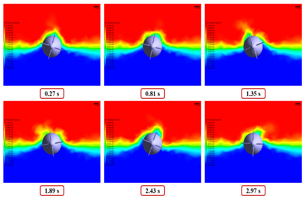
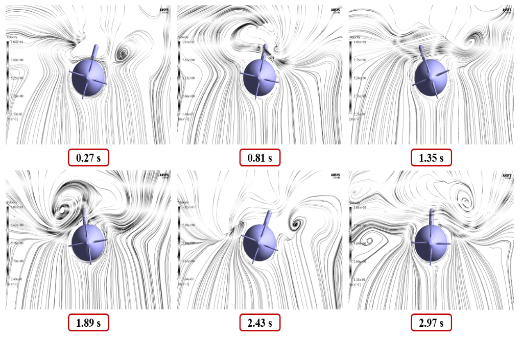
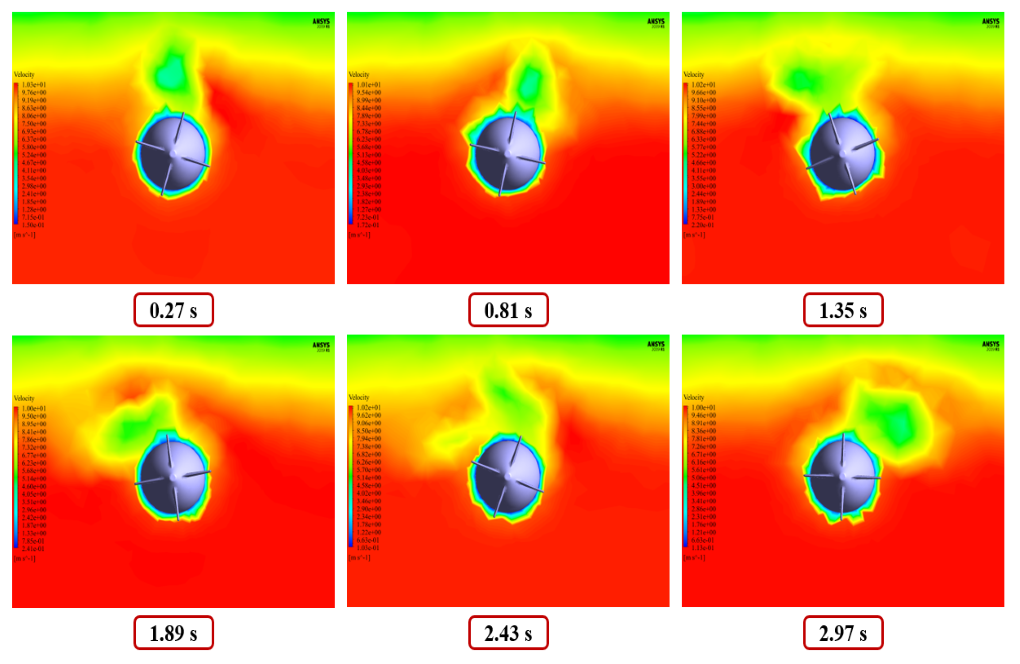
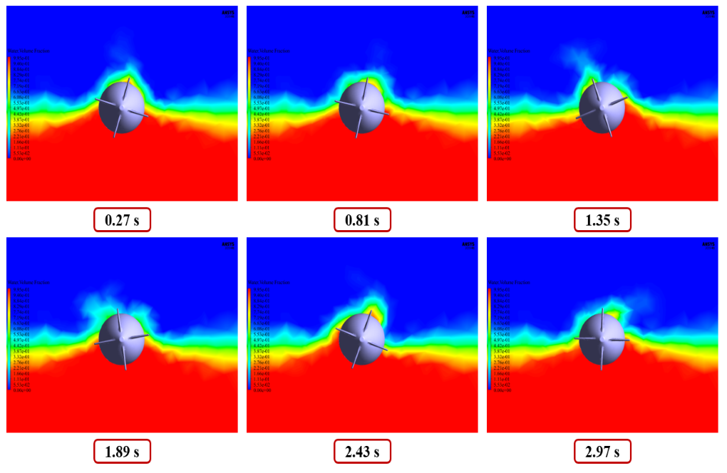
At the end of the solution process, we obtain two-dimensional contours related to the velocity and volume fraction of each of the water and air phases and two-dimensional path lines in the areas around the submarine.
We obtain these contours locally on a plane perpendicular to the horizontal axis of the submarine (parallel to the Y-Z plane).
We present these contours at different times of the simulation process. According to the defined UDF, the submarine rotates around its central axis (x-axis), and this rotational motion has clockwise and counterclockwise reciprocating motions over time.

Eldred Kemmer –
Can this simulation be used to optimize the design of the submarine?
MR CFD Support –
Absolutely, this simulation can be used as a tool for design optimization. By changing the design parameters of the submarine and observing the resulting behavior, you can identify ways to improve the design of the submarine.
Yesenia Metz –
How does the simulation model the turbulent flow in the fluid?
MR CFD Support –
The simulation models the turbulent flow using the k-epsilon turbulence model, which is a well-established model for simulating turbulent flows in CFD.
Rickey Runte –
Can this simulation be used to estimate the lifetime of the submarine?
MR CFD Support –
While the current simulation does not directly estimate the lifetime of the submarine, it can provide valuable insights into the stresses experienced by the submarine, which can be used to estimate its lifetime.
Brandt Nolan –
This dynamic mesh simulation is truly advanced. Being able to model the submarine’s motion and observe the reciprocal rotational motion effects is remarkable. Great job capturing the complex interactions between the submarine and the water medium!
MR CFD Support –
Thank you for your kind words! We’re glad to hear that our submarine simulation using dynamic mesh has met your expectations and provided valuable insights into fluid-structure interactions. It is always our goal to deliver detailed and accurate simulations. Your positive feedback is greatly appreciated!
Tiffany Frami –
I found the explanation about how the submarine rotates around its central axis very interesting. Thanks to the Dynamic Mesh method, can we also simulate other complex movements beyond this 1-DOF rotation, like pitch or roll?
MR CFD Support –
Absolutely! The Dynamic Mesh method in ANSYS Fluent is powerful enough to handle various kinematic motions, including pitch and roll, by defining additional degrees of freedom and corresponding UDFs (User-Defined Functions) to describe the movement. While our submarine simulation is limited to 1-DOF for rotation about the central axis, similar principles can be extended to create models with multiple DOFs, enabling us to simulate a wide array of complex movements of objects in fluid domains.
Mr. Bruce Hackett IV –
Is there a tutor or support available if I encounter problems understanding the UDF implementation for the submarine’s rotational motion?
MR CFD Support –
Our support team is always ready to assist our customers. If you have any difficulties with the UDF or any part of the simulation process, please reach out through our customer support channel, and one of our experts will be glad to help you understand and implement the UDF for the submarine’s motion correctly.
Ezekiel Buckridge –
Are the changes in mesh structure due to the movement of the submarine noticeably affecting the simulation accuracy?
MR CFD Support –
The dynamic mesh model accounts for the instantaneous change of meshing that could be critical as the submarine moves and interacts with the water. The ANSYS Fluent software adapts the mesh dynamically with smoothing and remeshing techniques to handle the deformation without compromising the accuracy. The simulation accounts for these mesh changes over time, maintaining high accuracy throughout the dynamic interaction.
Florian Reichel Sr. –
The UDF function for the submarine’s rotational motion seems complex. Is there support or tutorials available for creating similar functions for different scenarios?
MR CFD Support –
Yes, MR CFD Company offers resources and tutorials that provide guidance on creating User-Defined Functions (UDF) for various simulation scenarios. If you require a specific UDF for a different case, you may contact our support team or check for learning materials related to UDF programming in ANSYS Fluent on our website.
Royal Schmeler –
The tutorial was great in showing the dynamic behavior of the submarine! Could you provide insight on how the VOF model was specifically configured for managing two-phase flow around the moving submarine?
MR CFD Support –
Certainly! In this simulation setup, the VOF (Volume of Fluid) multiphase model is used to distinguish between the air and water phases within the computational domain. The model is configured so that the water is allocated below a certain level, creating the waterline, while above this level, the space is occupied by air. This meticulous allocation ensures proper interaction between the submarine and each phase respectively, as the submarine moves and affects water and air in its vicinity. Appropriate boundary conditions based on the VOF model are applied to capture the dynamics accurately, ensuring that the simulation reflects the realistic behavior of the water and the air responsiveness to the submarine’s rotational movement.
Carolyn Jacobi –
I mindfully watched how the submarine rotates in the simulation and it was fascinating! The attention to detail in this product is outstanding.
MR CFD Support –
Thank you for your kind words! We’re thrilled to know that the detailed simulation of the submarine movement captivated your attention. Your satisfaction with our product means a lot to us.
Jaron Davis –
I was completely fascinated by the level of detail covered in the ‘Submarine Movement in Water by Dynamic Mesh’ product. The interplay of fluid dynamics and submarine motion captured through CFD analysis clearly demonstrates the expertise of MR CFD Company. The use of the Dynamic Mesh method to account for the changing environment as the submarine maneuvers is impressive, truly bringing the simulation alive. Great job on illustrating the concepts with nuanced methodologies and results!
MR CFD Support –
Thank you for your positive feedback on our ‘Submarine Movement in Water by Dynamic Mesh’ simulation. It’s wonderful to hear that you found the detailed approach and the integration of the Dynamic Mesh method impressive and helpful for understanding fluid dynamics related to submarine movement. We take pride in providing high-quality, detailed simulations and are thrilled to learn that our efforts resonate well with our customers. Your enthusiasm for our product is highly appreciated!
Ryley Boyle V –
The stress and deformation maps acquired through the simulation accurately depicted the structural resilience of the submarine. It’s quite impressive how detail-oriented the analysis was, capturing the nuances of the dynamic interactions between the submarine and the water environment.
MR CFD Support –
Thank you for your thoughtful review! We are delighted to hear that you appreciated the depth of analysis in our submarine simulation. It’s always our goal to provide detailed and accurate simulations that capture the complex dynamics of the systems we model. Your feedback is greatly appreciated!
Prof. Berneice Rempel –
I’m really fascinated with the simulation level of detail. Does the submarine model take into account the variable buoyancy during its movement, or is it considered to have constant buoyancy?
MR CFD Support –
In this simulation, the submarine is considered to have only one degree of freedom, rotating around the x-axis. Variable buoyancy isn’t explicitly mentioned as a part of this specific motion; thus, the submarine is likely to have constant buoyancy as this detail would have been specified due to its potential impact on the dynamic behavior of the system.
Alyson Roob –
This learning material was incredibly detailed and offered profound insights into simulating submarine motion using ANSYS Fluent’s Dynamic Mesh method. The step-by-step approach made understanding the complexities of 1-DOF movements and interactions between the submarine and the water’s dynamic mesh intuitive. Great job, MR CFD Company!
MR CFD Support –
Thank you for your wonderful feedback! We are thrilled to hear that you found the material detailed and helpful. It’s great to know that the submarine simulation tutorial met your expectations and enhanced your understanding of Dynamic Mesh in ANSYS Fluent. We appreciate your recognition and look forward to providing you with more high-quality learning products!
Alexandria Konopelski –
Does the dynamic mesh technique account for changes in the submarine’s buoyancy during the simulation?
MR CFD Support –
In this particular simulation, the dynamic mesh technique is used primarily to simulate the movement and rotation of the submarine around its central axis; however, buoyancy effects are typically a part of the multiphase VOF model setup which would account for the submarine’s buoyancy in different fluid phases. The dynamic mesh allows the grid to adjust to the submarine’s rotation, but the buoyancy effects would rely on proper definition and interaction provided by the VOF model in conjunction with the dynamic mesh.