Supersonic Nozzle Flow Separation and Shock Wave
$80.00 Student Discount
- The present study simulates Supersonic Nozzle Flow Separation within a supersonic convergent-divergent nozzle.
- We design the 2-D model by the Design Modeler software.
- We Mesh the model by ANSYS Meshing software,
- We use a Density-Based solver to define the compressible flow.
- The mesh type is Structured, and the element number equals 9000.
To Order Your Project or benefit from a CFD consultation, contact our experts via email ([email protected]), online support tab, or WhatsApp at +44 7443 197273.
There are some Free Products to check our service quality.
If you want the training video in another language instead of English, ask it via [email protected] after you buy the product.
Description
Supersonic Nozzle Flow Separation (Shock Wave), ANSYS Fluent CFD Simulation Tutorial
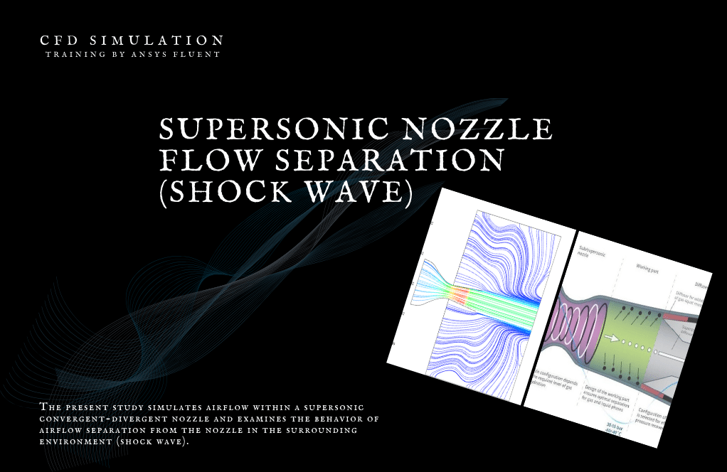
The present study simulates Supersonic Nozzle Flow Separation within a supersonic convergent-divergent nozzle. It examines the behavior of airflow separation from the nozzle in the surrounding environment by ANSYS Fluent software. We perform this CFD project and investigate it by CFD analysis.
The functional structure of the nozzle is such that as the fluid enters it and passes through the convergent part of the nozzle, according to the continuity equation, it causes the velocity of the passing fluid to increase by decreasing the cross-sectional area of the flow. Therefore, due to Bernoulli’s law, the fluid pressure decreases with increasing velocity.
Parameters such as Mach number, velocity, and pressure based on the fluid flow’s motion in the nozzle’s longitudinal direction have been investigated to analyze this model.
The following figure shows a schematic of the internal structure of a convergent-divergent nozzle and its components.
The present 2-D model is drawn using Design Modeler software. The geometric structure of the model consists of a convergent-divergent nozzle and the throat area, as well as a rectangular space containing the nozzle output.
The meshing of the present model has been done using ANSYS Meshing software. The mesh type is structured and the element number is 9000.
Supersonic Methodology
We have enabled a density-based solver due to the compressibility of this project. The nozzle pressure ratio (NPR) is equivalent to the ratio of the inlet air pressure of the nozzle to the ambient pressure.
Thus, the value of the nozzle pressure ratio in the current system is 1.5, and the amount of inlet air pressure is 153580.65 Pascals (NPR = P / P_ambient = 1.5 and therefore P = 1.5 * 102387.146), as well as the pressure at the output, is equal to the ambient pressure, that is 102387.146 Pascal.
In addition, the inlet airflow has a temperature of 290 Kelvin.
Supersonic Conclusion
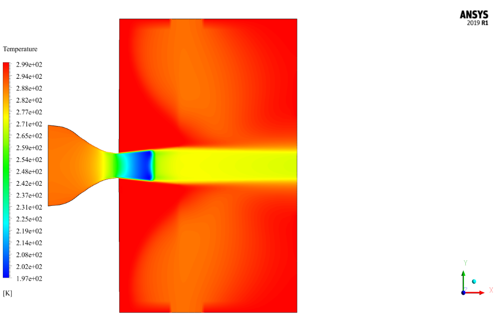
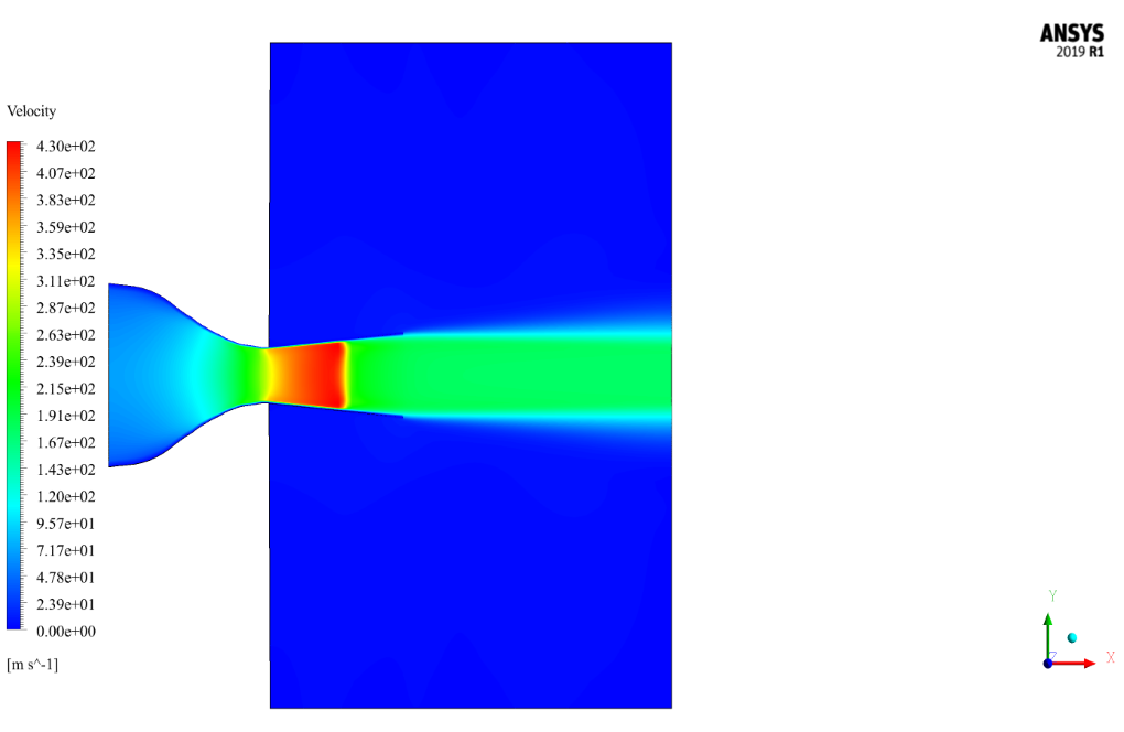
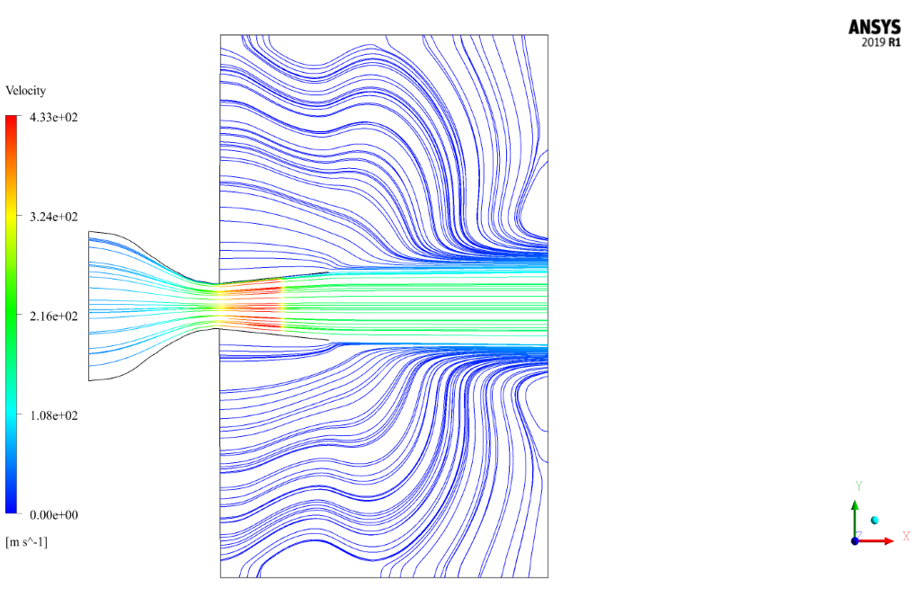
At the end of the solution process, we obtain two-dimensional contours of pressure, temperature, velocity, density, Mach number, and two-dimensional path lines.
As seen from the contours, Mach has increased in the nozzle opening. Therefore, it can be said that this type of nozzle, by changing the cross-section, causes the Mach number to enter along the range.
Increasing the Mach number in the nozzle opening reduces the pressure and reciprocally the temperature in the nozzle opening and therefore during the nozzle.




Pierce Reichel MD –
The use of CFD in this simulation is truly innovative!
Prof. Hayley Torphy DDS –
Can I contribute to this simulation?
MR CFD Support –
We are open to contributions! Please share your ideas or suggestions.
Donny Hane –
How are the results of the simulation visualized?
MR CFD Support –
The results are visualized using contour plots of temperature, pressure, velocity, and Mach number, as well as pathlines of the flow.
Abby Bernhard –
This tutorial looks like a real treasure trove for understanding airflow in nozzles. Do they show the effect of different NPRs on flow separation in the simulation results?
MR CFD Support –
Yes, in this tutorial, one of the focus points is to observe how variations in Nozzle Pressure Ratio (NPR) affect the flow separation inside the nozzle. The results include visuals like pressure and Mach number contours which can help you understand the changes in flow behavior under different NPR settings.
Jarrell Nienow –
This supersonic nozzle tutorial is detailed and it appears to meticulously cover each step used in the simulation process. The methodology indicates a clear understanding of the principles involved and effectively demonstrates the dynamics of flow separation and shock waves within a convergent-divergent nozzle.
MR CFD Support –
Thank you for your positive feedback about the Supersonic Nozzle Flow Separation and Shock Wave tutorial. We are glad that the detail and methodology met your expectations and aided in your understanding of the fluid dynamics in a convergent-divergent nozzle.
Mrs. Dovie Dickinson –
I’m really fascinated by the simulation of airflow separation and shock wave in this supersonic nozzle simulation. Could you elaborate on the reasons behind the flow separation within the nozzle?
MR CFD Support –
The flow separation within the supersonic nozzle is primarily due to the adverse pressure gradient encountered by the flow. When the supersonic flow decelerates to subsonic speeds past the throat of the nozzle, there is a build-up of pressure in the divergent portion. If this pressure gradient is strong enough and the flow is sufficiently imbalanced, it can lead to flow separation from the nozzle walls. The proper design and adjustment of the nozzle’s geometry, along with managing the pressure ratios, assist in reducing the risk of flow separation and the resultant shock waves.
Doug Sporer –
The tutorial explanation offers a lot of technical information. However, I didn’t quite understand the part about nozzle pressure ratio (NPR). Could you please explain how the NPR influences the flow within the nozzle and the significance of the chosen value of 1.5?
MR CFD Support –
Certainly! The nozzle pressure ratio (NPR) is a significant parameter in the performance of a supersonic nozzle. It is the ratio of the pressure of the gas at the nozzle inlet (P) to the ambient pressure (P_ambient). In supersonic nozzles, the flow behavior changes drastically with NPR, as it affects the flow’s ability to achieve supersonic speeds throughout the nozzle and its expansion in the divergent section. An NPR value of 1.5 means that the gas at the nozzle inlet is pressurized to 1.5 times the ambient pressure. If the NPR is above a certain critical value, which depends on the specific geometry of the nozzle, the flow will reach and maintain supersonic speeds past the throat and throughout the divergent section. The chosen value of 1.5 suggests the intent to create a condition where supersonic speeds are achieved, leading to the observed flow characteristics such as the expansion waves, flow separation, and possibly shock waves. These features and their respective influences on the velocity, pressure, and temperature are critical for analyzing the nozzle’s performance in supersonic conditions.
Kirsten Herman II –
This sounds like an advanced simulation! I’m curious about how the shockwave formation is visualized in the CFD results. Is there a specific contour or parameter that highlights the shockwave clearly?
MR CFD Support –
In the results of this simulation, shockwaves are generally visualized by contours of pressure, density, or Mach number. In supersonic flows, sudden jumps in these parameters indicate the presence of shockwaves. The pressure contour will show a steep gradient, and the Mach contour will drop across the shock demonstrating supersonic to subsonic transition.
Jamil Kohler Sr. –
I’m very impressed with the level of detail in the Supersonic Nozzle Flow Separation and Shock Wave simulation tutorial. The explanations make it easy to understand complex phenomena like shock waves and velocity changes within the convergent-divergent nozzle structure. Well done!
MR CFD Support –
Thank you for your kind words about the Supersonic Nozzle Flow Separation and Shock Wave simulation tutorial. We are thrilled to hear that the tutorial was clear and informative. Our goal is always to make complex topics accessible and understandable, and we’re glad that we could achieve that for you. If you have any more questions or need further assistance, please don’t hesitate to reach out.