Ogee Spillway CFD Simulation, ANSYS Fluent Training
$80.00 Student Discount
- The problem numerically simulates the Ogee Spillway using ANSYS Fluent software.
- We design the 3-D model by the Design Modeler software.
- We Mesh the model by ANSYS Meshing software, and the element number equals 10959.
- We use the VOF Multi-Phase model to define water and air in channels.
To Order Your Project or benefit from a CFD consultation, contact our experts via email ([email protected]), online support tab, or WhatsApp at +44 7443 197273.
There are some Free Products to check our service quality.
If you want the training video in another language instead of English, ask it via [email protected] after you buy the product.
Description
Description
This simulation is about the Ogee spillway via ANSYS Fluent software. We perform this CFD project and investigate it by CFD analysis.
The main task of this type of structure (spillway) is to remove excess water in situations such as a flood that water flow damages the dam body. The structure of these spillways consists of a vertical plate in the flow direction of the fluid, whose upper edge can be both sharp, curved, and wide.
Spillways have several types: open channel, chute, stepped, siphon, ogee, side channel, labyrinth, and so on. The purpose of the present study is to investigate the behavior of water flow after passing through an ogee spillway in the presence of airflow.
The geometry of the present model is drawn by Design Modeler software. The geometry of this model consists of a horizontal cylinder. It has a horizontal inlet for mixture flow and two vertical outlets for separated gas and liquid flows.
The model is then meshed by ANSYS Meshing software. The model mesh is unstructured, and 10959 cells have been created.
Ogee Spillway Method
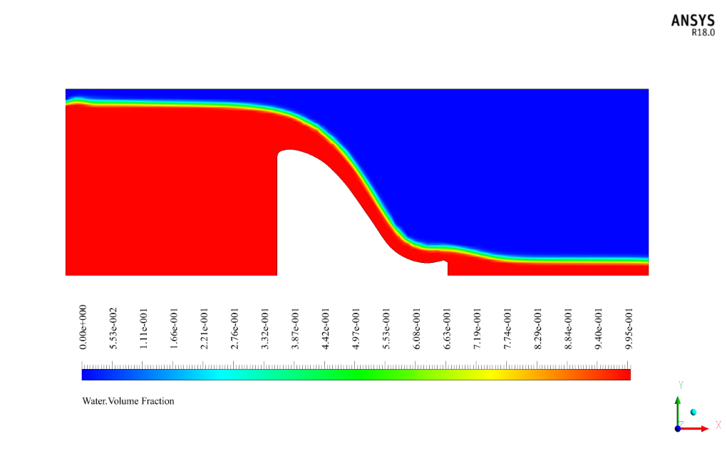
Since the channel uses two different flows, the two-phase flow model is used. The two-phase VOF (volume of fluid) model is used in this simulation to define the water as the primary phase and the air as the secondary phase.
Since the phase separation boundary is completely distinct, the Volume of Fluid (VOF) model is used. The sharp type in interface modeling has been used to determine the behavior at the boundary between two phases.
Ogee Spillway Conclusion
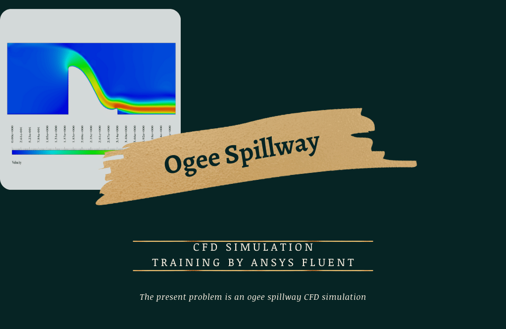
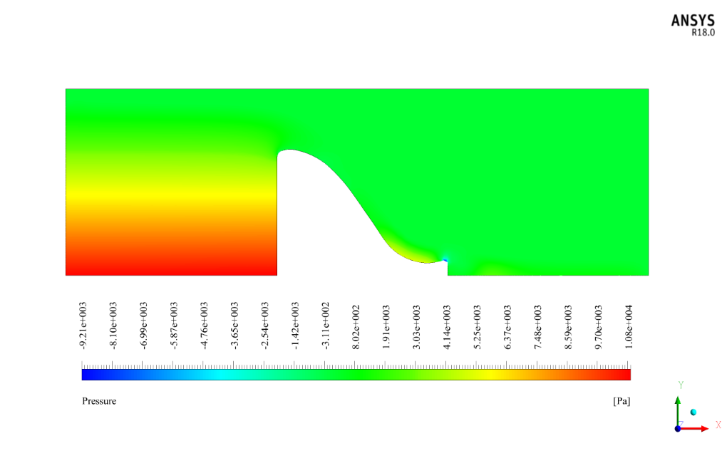
After simulation, the contours of velocity, pressure, and mass fraction of water and air are obtained. The contours show that the water flow hits the dam body and starts to overflow from its upper edge.
Then the excess water flow slides on the spillway slope and moves downwards with low pressure. This will prevent the strength and intensity of the flood.


Laurine Schamberger –
How does the simulation handle the interaction between the water and air?
MR CFD Support –
The simulation uses the Volume of Fluid (VOF) model to accurately capture the interaction between the water and air, including the formation of air bubbles and the behavior of the free surface.
Mrs. Bonita Leffler –
Can this simulation help in predicting erosion or structural damage in an actual spillway?
MR CFD Support –
While the simulation’s main focus is fluid dynamics, the results can provide insights into potential areas of high pressure or velocity that could lead to erosion or structural damage over time.
Wallace Gleichner –
I’m interested in a simulation of a stepped spillway. Can you accommodate that?
MR CFD Support –
Sure! We can certainly help with simulations of stepped spillways. Please provide more details about your requirements, and we’ll do our best to accommodate your request.
Garry McCullough –
I’ve seen some impressive images of the water flow captured in these spillway simulations. How is the real_LOOK of water and air during overflow condition rendered in the results, especially considering the complexity of capturing the air-water interface?
MR CFD Support –
Graphical rendering of water and air in simulations like the ogee spillway is achieved through post-processing tools offered in ANSYS Fluent. Specifically, the VOF model along with interface capturing methods provides clear delineation of the phases. It yields realistic visualizations of water flow and air-water interface, highlighting areas of significant aeration and turbulence. Contour plots, pathlines, and vector fields illustrate the physics with high fidelity, and specialized rendering features and shaders contribute to the photorealistic appearance of the fluids.
Miss Makenzie Herzog –
Very impressed with the detailed simulation of the Ogee spillway in ANSYS Fluent. The understanding of multiphase flow and control during potential flood conditions is crucial, and it seems like this training covered it well!
MR CFD Support –
Thank you for your kind words. We are glad to hear that you found the Ogee spillway simulation detailed and informative. Understanding multiphase flows and effective management during high-water events is indeed crucial, and we are happy that our training met your expectations. If you have any more feedback or need further information, please feel free to reach out to us.
Dr. Murphy Volkman V –
The Ogee Spillway CFD simulation was both educational and practical for understanding fluid dynamics over complex structures. In the modeled scenario, observing the water and air interactions provided valuable insights. Would love to know more simulations training courses like this one!
MR CFD Support –
Thank you for your positive feedback on the Ogee Spillway CFD simulation training. We’re delighted to hear that it provided you with valuable insights into fluid dynamics. Stay tuned to our offerings, as we continuously update our course list with new and comprehensive simulations to broaden your knowledge in CFD application.
Lawson Ortiz –
The simulation was very informative. Great visualization of water and air interactions with clear display of the spillway dynamics.
MR CFD Support –
Thank you for your kind words! We’re glad to hear that our simulation on the Ogee Spillway provided you with clear and informative visualizations. If there are any more aspects of CFD you wish to learn about, feel free to explore our other training products.
Beaulah Gibson –
I’ve always been fascinated by the practical application of spillways. Could you please clarify how the VOF model ensures that the boundary between the air and water phases remains sharp during simulations?
MR CFD Support –
The VOF model assigns a volume fraction for each phase in every computational cell and reconstructs the interface between the different phases. In the simulation with a sharp type interface modeling, the reconstruction of the interface is ensured to be as sharp as possible by applying specific discretization and surface tension treatments, maintaining clear boundaries between distinct fluids like air and water.
Miss Ivory Gibson III –
Can this simulation be used for spillways of different shapes and sizes?
MR CFD Support –
The simulation setup can be adapted to study spillways of different shapes and sizes. The geometry and mesh can be modified to match the specific design of the spillway.
Vladimir Murazik –
I am very impressed by the broad scope covered in the Ogee Spillway CFD Simulation course using ANSYS Fluent. The detailed explanation of the different spillway types and the method used to analyze water and air interaction is outstanding. The practical setup and results offer an in-depth understanding of fluid behavior in complex situations like a flood. An amazing learning tool for engineers and researchers!
MR CFD Support –
We’re thrilled to read your positive feedback on the Ogee Spillway CFD Simulation course. It’s great to know that our product is making a significant impact on your learning experience. We aim to provide detailed and practical understanding in each of our training products, and we appreciate you taking the time to acknowledge this. Thank you for recognizing our efforts, and we look forward to continuing to serve you with high-quality educational materials.
Zita Bogisich –
I’m impressed by the range and decisiveness of the simulations you’re able to perform! The Ogee Spillway simulation particularly caught my attention; it must be fascinating to watch the water’s behavior visualized through the software. Fantastic work!
MR CFD Support –
Thank you for your kind words and enthusiasm about the Ogee Spillway CFD Simulation! We’re thrilled that you found the visualization of the water’s behavior captivating—it’s our aim to provide detailed and insightful simulations for our users. If you have any further thoughts or need assistance with another project, don’t hesitate to reach out.
Eddie Cronin –
I recently completed the Ogee Spillway CFD simulation using ANSYS Fluent, and the level of realism achieved was impressive. It was fascinating to see how expertly the two-phase VOF model handled the interaction between the air and water flows, providing detailed insight into the water’s behavior over the spillway during flood conditions.
MR CFD Support –
We greatly appreciate your positive feedback! It’s wonderful to hear that our simulation was able to provide you with a detailed and realistic understanding of spillway dynamics. Your satisfaction with the level of detail in the interaction of air and water flows during the use of the two-phase VOF model encourages us in our efforts to offer high-quality CFD simulations. Thank you for choosing our training product!
Mr. Lafayette Morar MD –
The tutorial on simulating an Ogee spillway with ANSYS Fluent was terrific. The detailed breakdown of the methodology helped me better understand two-phase flow simulation using the VOF model. Incredible work!
MR CFD Support –
Thank you for your positive feedback! We’re thrilled that our Ogee spillway simulation tutorial was helpful to you and that you were able to gain a better understanding of two-phase flow simulation with the VOF model in ANSYS Fluent. Your comments made our day! If you have any further questions or need assistance with your CFD projects, feel free to reach out.
Cielo Willms –
This course gave me a solid understanding of Ogee spillway simulation in ANSYS Fluent. The step-by-step instructional style really made the complex concepts easy to grasp!
MR CFD Support –
Thank you for your positive feedback! We’re thrilled to hear that our instructional approach proved effective for you. It’s our goal to break down complex subjects into understandable increments. If you have any more questions as you continue to learn, don’t hesitate to reach out!
Luther Christiansen –
The detailed fluid dynamics of the ogee spillway, as shown in the results, demonstrate CFD’s capability to accurately predict real-world scenarios. Combining air and water phases in the simulation provides valuable insights for infrastructure safety and design.
MR CFD Support –
Thank you for taking the time to provide feedback on our Ogee Spillway CFD Simulation training product. We are thrilled that it offered you valuable insights and that you appreciate the level of detail provided in the fluid dynamics analysis. Your satisfaction with our products is our top priority!
Francis Goldner –
I’m impressed by the elaborate study on the Ogee Spillway CFD Simulation. Was the interface boundary between the air and water phase easy to discern in the simulation results?
MR CFD Support –
Thank you for your complimentary words! Yes, in the simulation, the interface boundary between the air and water phases was captured with clarity, allowing for accurate analysis of the spillway behavior. The Volume of Fluid (VOF) model in ANSYS Fluent is particularly adept at tracking the interface in bifluid flows, ensuring detailed and precise results.