Zigzag Channel with Flow Pulsation, Paper Numerical Validation, ANSYS Fluent Training
Free
- The problem numerically simulates the Zigzag Channel with Flow Pulsation using ANSYS Fluent software.
- We design the 3-D model with the Design Modeler software.
- We mesh the model with ANSYS Meshing software, and the element number equals 144713.
- The Energy Equation is activated to consider heat transfer.
- This simulation is validated with a reference article.
Click on Add To Cart and obtain the Geometry file, Mesh file, and a Comprehensive ANSYS Fluent Training Video.
To Order Your Project or benefit from a CFD consultation, contact our experts via email ([email protected]), online support tab, or WhatsApp at +44 7443 197273.
There are some Free Products to check our service quality.
If you want the training video in another language instead of English, ask it via [email protected] after you buy the product.
Description
Description
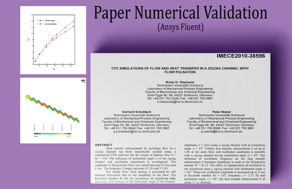
The present problem simulates the flow of water passing through a canal in a zigzag pattern by ANSYS Fluent software. The simulation is based on a reference paper, “CFD SIMULATIONS OF FLOW AND HEAT TRANSFER IN A ZIGZAG CHANNEL WITH FLOW PULSATION,” and its results are compared and validated with the results in the article.
The channel model is such that the number of stages of channel oscillation in the horizontal direction equals 10. The channel angle in each of these ten stages for modeling is assumed to be 15 degrees.
The inlet velocity of water flow in different models varies based on the Reynolds value. However, the inlet water flow temperature in all models equals 293.15 K. The lower wall of the zigzag channel is insulated. The upper wall has a constant temperature of 276.65 K.
The present model is drawn in three dimensions using Design Modeler software. Also, the width of the channel or the vertical distance between the upper and lower walls is assumed to be equal to 8 mm, and the depth of this channel is equal to 1 mm.
The meshing has been done using ANSYS Meshing software, and the mesh type is unstructured. The element number is 144713, and a boundary layer mesh is used on the upper and lower walls of the canal.
Zigzag Channel Methodology
Several different Reynolds values, including 53, 107, 191, 266, 320, 427, and 534, were used for this simulation; Therefore, due to the low Reynolds numbers, the flow in all models is defined as laminar.
Zigzag Channel Conclusion
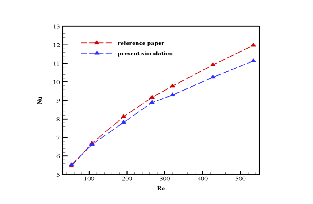
The main purpose of the problem is to investigate the amount of Nusselt numbers in the vicinity of the upper wall of the channel. At the end of the solution process, the value of the Nusselt number in different Reynolds simulations was obtained, compared, and validated with the values in the diagram in Figure 6 of the reference paper.
The desired Nusselt number is obtained using the software report on the top wall of the model, which has a constant temperature boundary condition. Of course, in determining the Nusselt number, we must pay attention to the values in the Reference Value section of the software.
For example, in this model, the length is twice the channel cross-section, and the reference Temperature is equal to the average of the inlet and outlet temperature of the flow.
| Re | Velocity inlet | Nu |
| 53 | 0.0033 | 5.5198 |
| 107 | 0.0067 | 6.6144 |
| 191 | 0.0119 | 7.8173 |
| 266 | 0.0167 | 8.8823 |
| 320 | 0.0201 | 9.2883 |
| 427 | 0.0268 | 10.2589 |
| 534 | 0.0335 | 11.1337 |
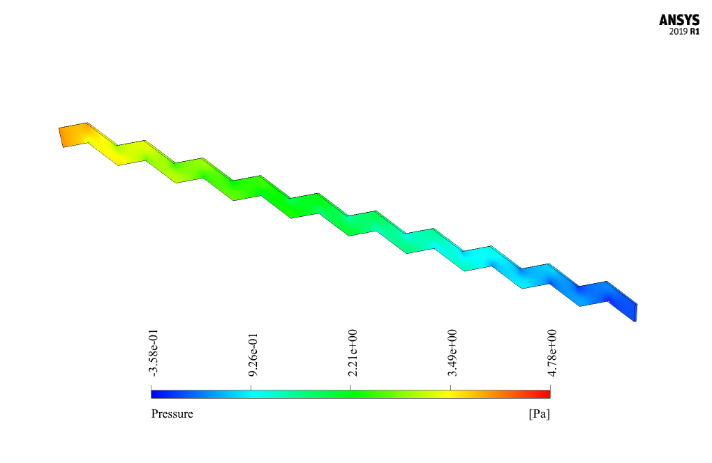
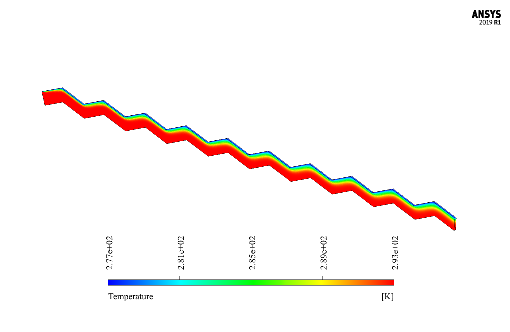
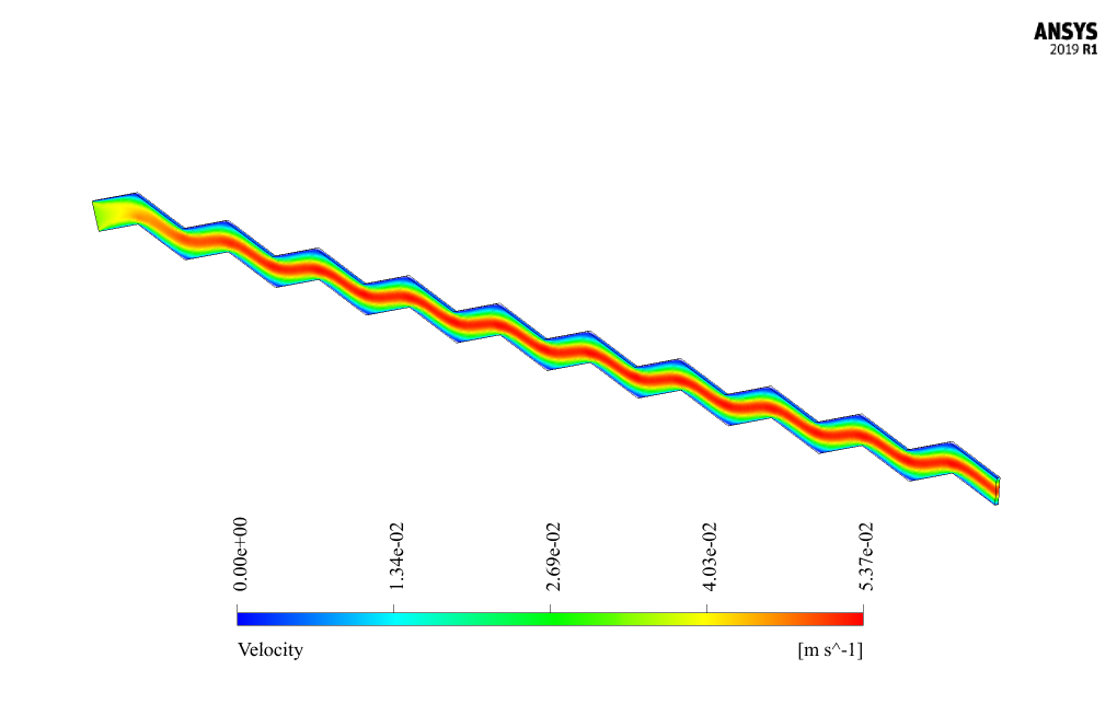
Also, at the end of the solution, three-dimensional velocity, pressure, and temperature contours are obtained and analyzed for three different Reynolds values, including 53, 266, and 534.
Derek Corkery –
Can you explain how the flow pulsation is considered in this zigzag channel simulation in ANSYS Fluent?
MR CFD Support –
In the zigzag channel simulation for pulsating flow, a transient simulation set-up is often employed. This involves specifying oscillating inlet velocity boundary conditions over time to create the flow pulsation effect. The velocity versus time profile would be derived based on the study’s requirements, ensuring it matches the conditions described in the reference paper for accurate results.
Dr. Cordelia Buckridge –
How does the variation in Reynold’s number impact the simulation results, particularly about heat transfer and flow patterns?
MR CFD Support –
The variation in Reynolds number affects the simulation results by changing the flow characteristics within the zigzag channel. Higher Reynolds numbers typically indicate a more turbulent or vigorous flow, which can enhance mixing and heat transfer, leading to higher Nusselt numbers. As composition is very much accepted best customer.
Mrs. Aracely Turcotte Sr. –
What an incredible learning resource! I managed to set up the zigzag channel simulation and follow through with the flow pulsation, closely reproducing the results from the reference paper. Learning about how to simulate different Reynolds numbers was particularly fascinating. It successfully demonstrated the heat transfer and flow changes, which helped solidify my understanding of the Nusselt number concept in such configurations.
MR CFD Support –
Thank you so much for your kind words! We are thrilled to hear that you found the simulation useful and that it enhanced your understanding of the heat transfer and flow dynamics in zigzag channels. It’s great that the course material enabled you to replicate the results of the study accurately. If you ever have any questions or need further assistance with our simulations, please don’t hesitate to reach out.
Karina Nolan –
The channel’s upper wall has a constant temperature during simulations. Why is that so, and how does it affect the results?
MR CFD Support –
The upper wall’s constant temperature represents a controlled thermal boundary condition often used in experiments for heat transfer analysis. It permits the precise measurement of the Nusselt number along the wall and helps understand the effects of convection and report consistency. In terms of result impact, it ensures that any changes in the heat transfer rate (represented by the received Nusselt number) directly result from changes in the fluid flow behavior rather than variations in the thermal input.
Raoul Ondricka –
I completed the training on modeling a Zigzag Channel with Flow Pulsation and must say I was blown away by how well it matched the results of the reference article that was used for validation. The step-by-step guidance made everything clear, and seeing the simulation results nearly mirroring the real-world data gave me a lot of confidence in the learning provided!
MR CFD Support –
We’re thrilled to hear that our training on Zigzag Channel with Flow Pulsation met your expectations and helped build your confidence in the simulation. Feedback like this validates our commitment to providing high-quality and accurate training content. Thank you for taking the time to share your experience—we truly appreciate it!
Greta Ullrich –
The product discription was fascinating! The degree of accuracy achieveable in simulating the Nusselt number variations across varying Reynolds numbers is impressive, especially given its importance in thermal analysis. Learning how to validate simulations with published research improves reliability and trust in simulation results. Can this learning product be used to ensure similar outcomes for different channel designs or flows with more complex properties?
MR CFD Support –
Thank you for your positive feedback! We are glad to hear that you are impressed with the accuracy of the simulation and its validation process. Our trainer modules are constructed to teach comprehensive simulation techniques that can be applied to a variety of scenarios. For different channel designs and more complex flow properties, the fundamental principles taught can be adapted, however, outcomes might vary based on the specific details of each case. It’s encouraged to consider the training as a robust foundation which can be built upon with further experiments and simulations tailored to other complex scenarios.