Heat Recovery in Counter and Cross Flow Plate Heat Exchangers, Paper Numerical Validation
$200.00 Student Discount
- The problem numerically simulates a cross-flow heat exchanger plate panel using ANSYS Fluent software.
- We design the 2-D model with the Design Modeler software.
- We Mesh the model with ANSYS Meshing software.
- The mesh type is Structured, and the element number equals 155000.
- This project is simulated and validated with a reference article.
To Order Your Project or benefit from a CFD consultation, contact our experts via email ([email protected]), online support tab, or WhatsApp at +44 7443 197273.
There are some Free Products to check our service quality.
If you want the training video in another language instead of English, ask it via [email protected] after you buy the product.
Description
Heat Recovery in Counter and Cross Flow Plate Heat Exchangers, Paper Numerical Validation, CFD Simulation by ANSYS Fluent
The present problem is an ANSYS Fluent software CFD simulation of a cross-flow heat exchanger plate panel.
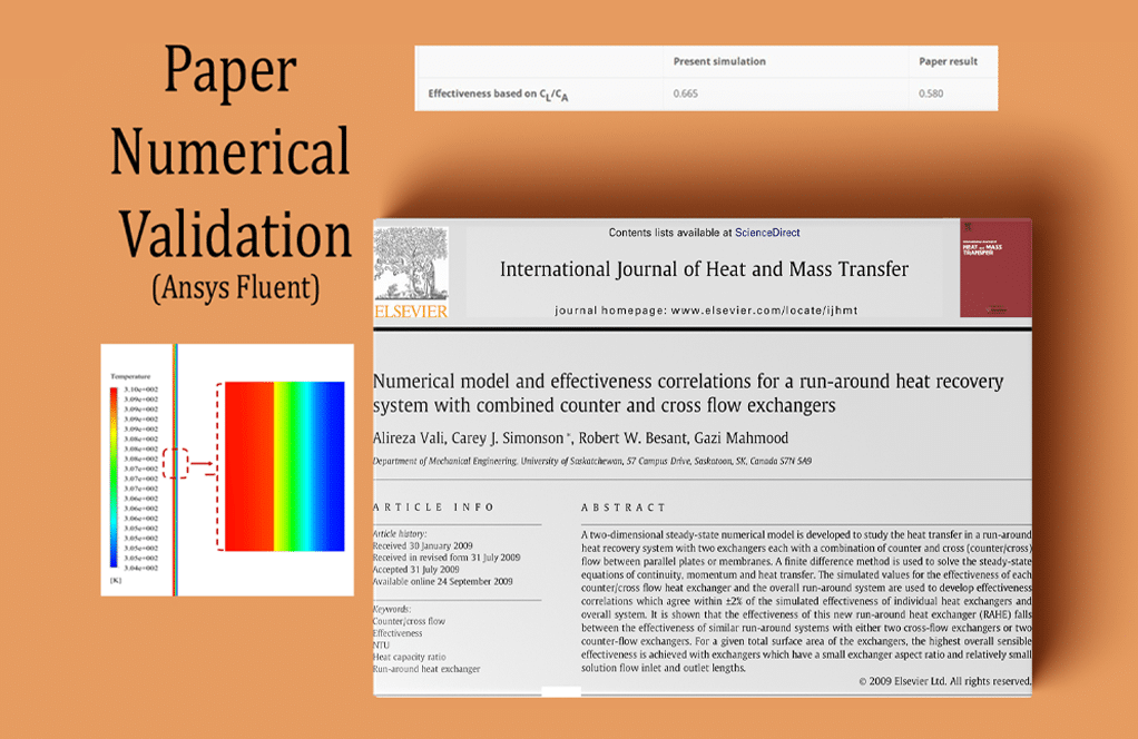
This simulation is based on the data in the reference article “Numerical model and effectiveness correlations for a run-around heat recovery system with combined counter and cross-flow exchangers,” The results are compared and validated with the results in the paper.
This heat exchanger consists of two special flow channels; In this way, the airflow flows from one side of the panel’s central panel, and the solution flows from the other side but in the opposite direction to the airflow.
This panel generally belongs to one of the two panels in the closed cycle of solution and airflow. The fluids used in the present model include air and ethylene glycol (CH2OH), although their thermophysical properties are manually defined in the Fluent.
Ethylene glycol is a colorless, odorless, low volatility, low viscosity material whose properties are temperature-dependent polynomials. Also, since hot and cold flows are not integrated into this heat exchanger, there is no need to use a multiphase flow module, and on the other hand, a separating plate is used as an interface.
CFD Methodology
The geometry of the present model is designed in three dimensions using Design Modeler software.
The meshing has been done using ANSYS Meshing software, and the mesh type is structured. The element number is 155000. The cells near the wall boundaries are smaller and more accurate.
Exterior walls also act as insulation.
Heat Recovery in Counter and Cross Flow Plate Heat Exchangers Conclusion
The solution fluid in the model has a temperature higher than the airflow; therefore, the purpose of the problem is to cool the hot air flow outlet. The general purpose of the present problem is to study the fluid behavior and heat transfer of the flows and investigate the heat exchanger’s performance efficiency.
At the end of the simulation process, the efficiency of the heat exchanger is calculated, compared, and validated with the value obtained in the reference paper. This comparison and validation are based on the values in the diagram in Figure 11 of the article.
This diagram shows the changes in the heat exchanger efficiency (Ԑ) in the ratio xi / x0. This ratio xi / x0 is defined as the ratio of the liquid flow inlet length to the heat exchanger’s total length. According to the modeled geometry of the present numerical simulation, the value of this ratio in the current work is 0.1.
The relationships in the paper are used to calculate the heat exchanger efficiency. The amount of air and liquid inlet temperature was defined in the boundary conditions.
The outlet temperature of the air and fluid was obtained. It should be noted that the heat transfer from the cold fluid to the hot fluid during the simulation process equals the heat transfer from the hot fluid to the cold fluid.
| Present simulation | Paper result | |
| Effectiveness based on xi/x0 | 0.665 | 0.716 |
Also, according to the relations and calculations mentioned above, the ratio of the heat capacity of the liquid to the air can be calculated. According to the diagram in Figure 19, the efficiency of the heat exchanger can be obtained in the amount of the mentioned ratio and be compared with the calculated efficiency according to the above relations.
| Present simulation | Paper result | |
| Effectiveness based on CL/CA | 0.665 | 0.580 |
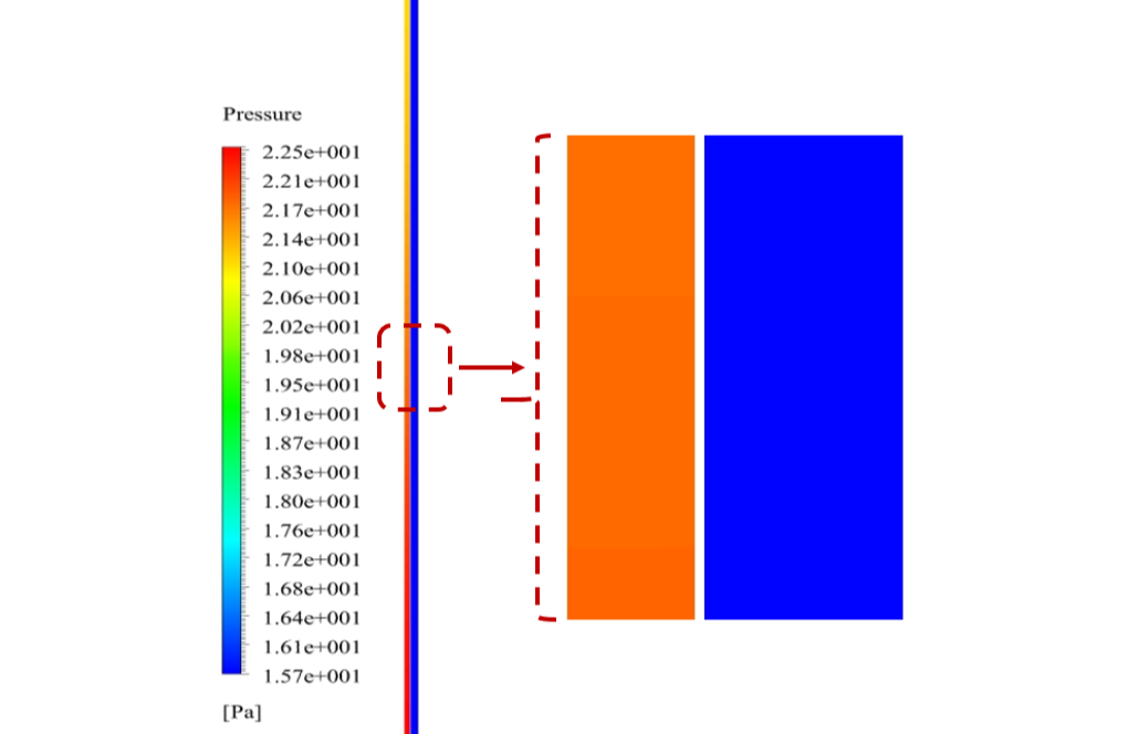
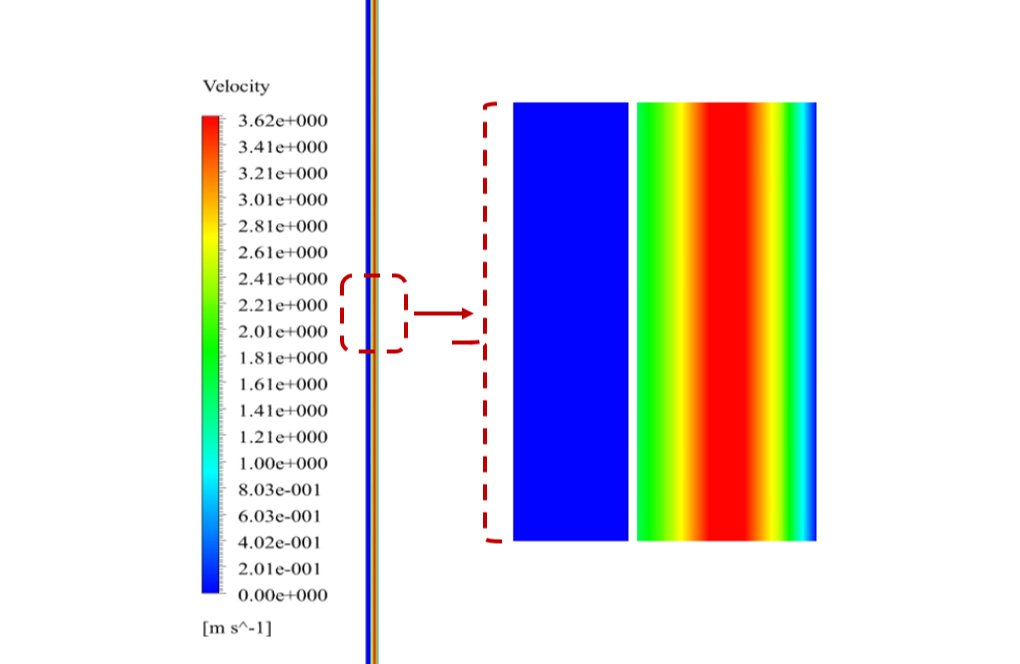
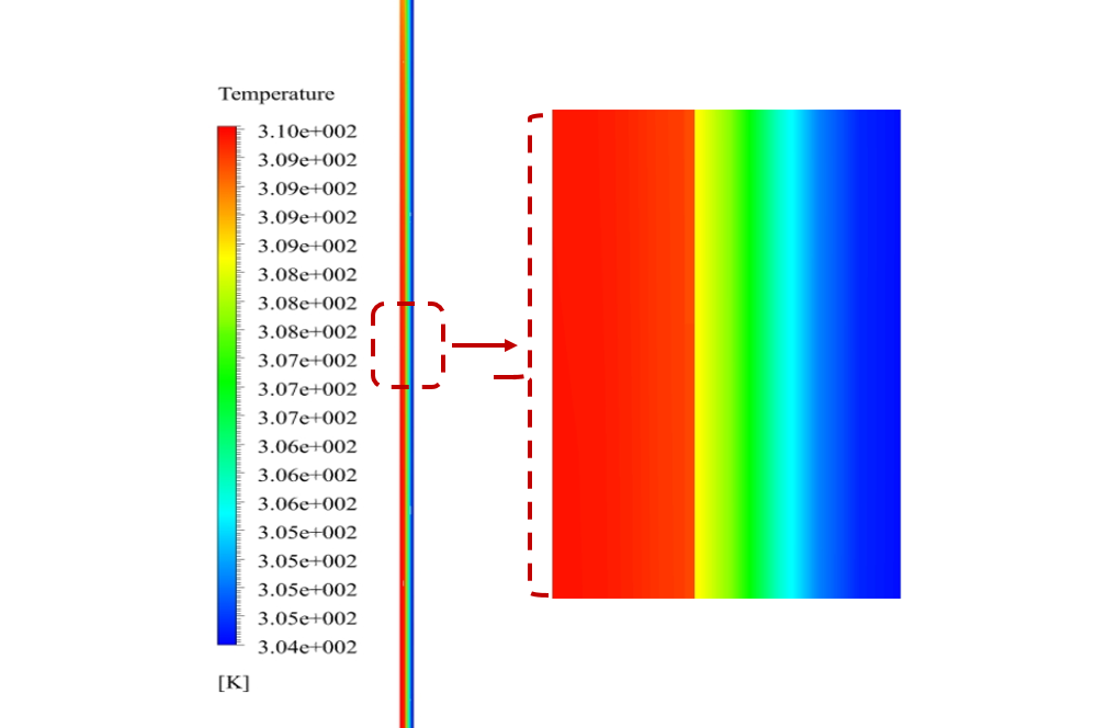
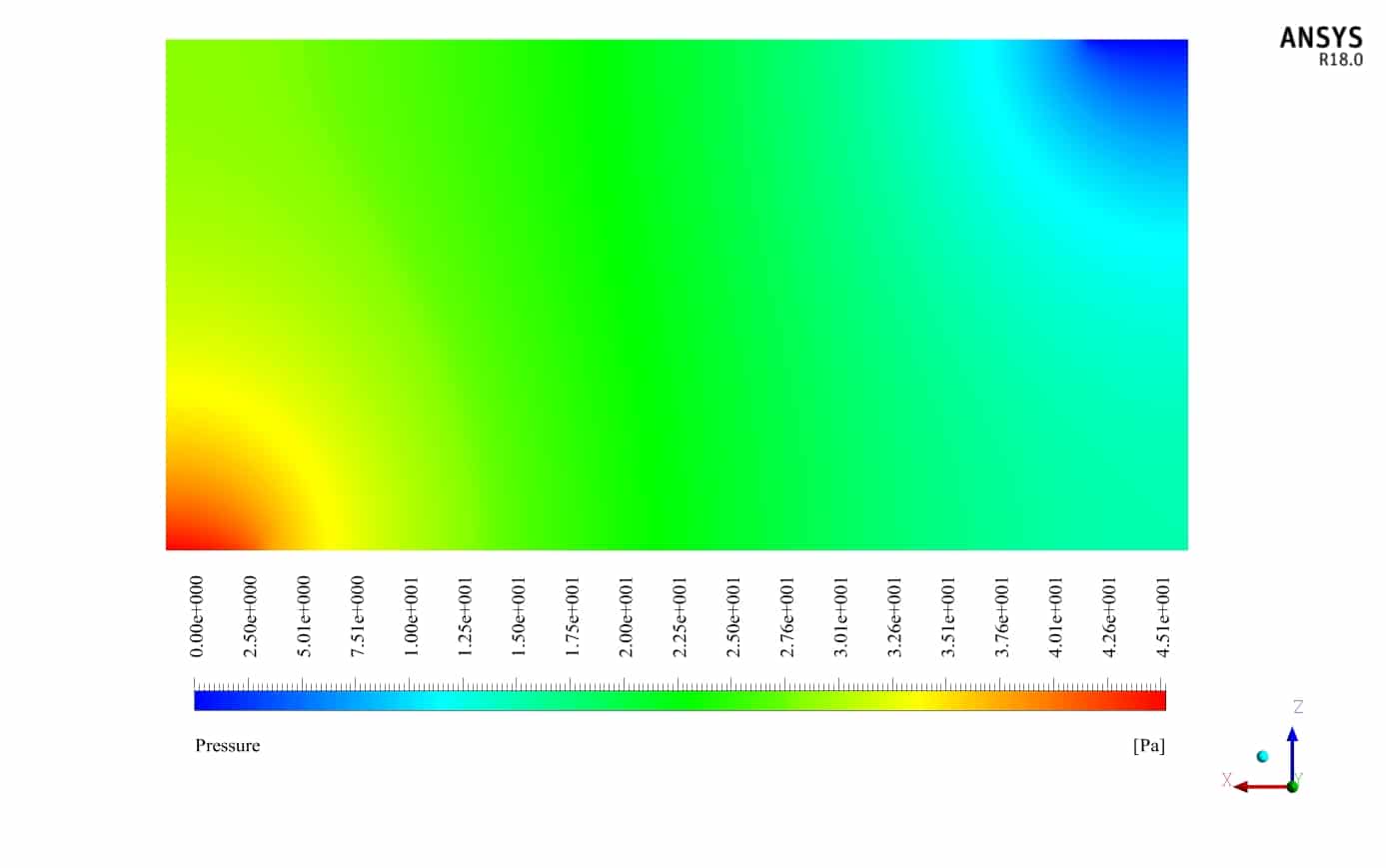
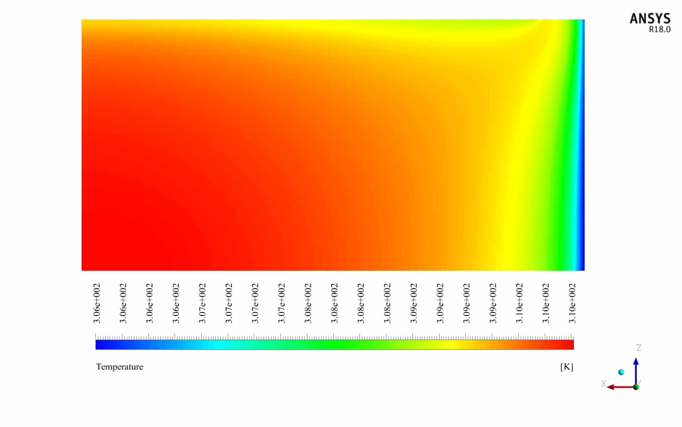
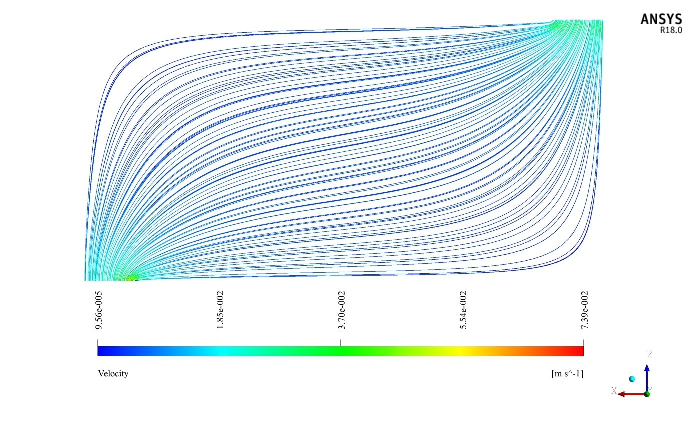
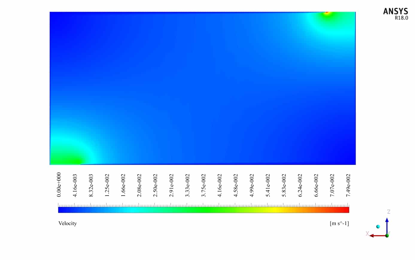
Also, two-dimensional contours related to temperature, pressure and velocity have been obtained in two sections, X-Z and Y-Z, and two-dimensional path lines.


Mrs. Rylee Padberg –
The results of the CFD simulation were close, but different from the paper’s data. Could you explain what might cause this difference in effectiveness?
MR CFD Support –
Variations in heat exchanger effectiveness between the numerical simulation and reference paper could be due to several factors, including slight differences in the boundary conditions setup, the simplifications made in the numerical model, the mesh size and quality, numerical discretization schemes, or potential errors in the experimental data or their interpretation in the reference paper.
Keon Kreiger –
I was impressed by the accuracy of your simulation compared to the reference paper results! Could such a heat exchanger be used in a residential HVAC system to improve energy efficiency?
MR CFD Support –
Yes, such a heat exchanger could be scaled and tailored to work within a residential HVAC system for energy recovery, which would significantly improve the overall energy efficiency by transferring heat from the exhaust air to the incoming fresh air stream.
Kellie Weimann –
I found the detail on inlet temperatures of air and fluid crucial for understanding the initial conditions. Could you please specify what temperatures were set for these inputs in the simulation?
MR CFD Support –
In this simulation, the air and solution (ethylene glycol) inlet temperatures were chosen in line with the reference paper’s data to ensure accurate validation. For airflow temperature, we might start with a typical ambient condition unless specified otherwise, and ethylene glycol might have a higher initial temperature due to heat recovery expectations. Precise values, however, aren’t provided in the summary given. Therefore, for an exact replication or deep understanding of initial conditions, one would indeed refer directly to the temperature values used in the reference article itself.
Charlotte Mraz –
I’m thoroughly impressed by the level of detail put into validating this CFD simulation against the reference paper data. The effort to match Xi/X0 and CL/CA ratios for judgment of effectiveness adds robustness to the study. Was any sensitivity analysis on mesh or boundary conditions done to further ensure the accuracy of the simulation?
MR CFD Support –
Admin here! In CFD simulations such as this, a mesh independence study is often performed by refining the mesh until the variation in results becomes negligible. Additionally, sensitivity analysis on boundary conditions could be done to verify the sensitivity of the outcomes to variations in the applied conditions. However, these specific analyses are not detailed in the provided description. Typically, they serve to strengthen confidence in the simulation’s predictive accuracy.
Randi Bogan –
I’m delighted with the comprehensiveness of the simulation study especially in terms of the data validation with an existing paper. How are errors between the simulation results and paper controlled and minimized?
MR CFD Support –
Thank you for your feedback. In the simulation, errors are controlled and minimized through careful calibration of the model, including the definition of thermophysical properties, refinement of mesh to ensure numerical accuracy, validation steps with experimental or published data, and sensitivity analysis of various parameters. Ensuring numerical schemes’ stability and convergence also play crucial roles. Furthermore, the simulation settings are aligned as closely as possible with the conditions detailed in the reference article.
Alvah Williamson –
It’s clear from the description that the validation with the reference paper was important in this simulation. Could you explain how closely the simulation results matched with the paper and what difference such validation makes in terms of reliability?
MR CFD Support –
In the simulation, the results were found to be very close to those documented in the reference paper. Specifically, the effectiveness based on xi/x0 yielded a value of 0.665 in the simulation as against 0.716 in the paper, while the effectiveness based on CL/CA was the same in both at 0.665. This high level of agreement indicates a high degree of accuracy in the computational model, enhancing its reliability for predicting real-world performance.
Terrill Reichert –
The product you reviewed is outstanding in describing the CFD methodology and final outcomes. The attention to detail and comprehensive validation approach provides great assurance that learners will gain accurate and practical insights while using this software. Bravo, MR CFD Company!
MR CFD Support –
Thank you for your kind words! We’re thrilled to hear that you’re satisfied with the accuracy and detail of our CFD simulation for heat exchanger efficiency. We strive to ensure our products are both educational and practical. Your feedback is much appreciated!
Pearlie Mann –
Thank you for the in-depth CFD resources! The comparison with published papers helped a lot in validating my own simulations. How crucial was it to have an accurate grid, and do you have suggestions for someone new to meshing for such simulations?
MR CFD Support –
In CFD simulations, particularly for heat exchanger analysis, an accurate and refined grid is crucial to accurately capture the heat transfer and fluid flow phenomena. For someone new to meshing, it’s important to ensure that the grid is fine enough in areas of high thermal or velocity gradients while ensuring the overall number of elements remains manageable for computational efficiency. Starting with a mesh independence study is recommended to find the right balance.
Miguel Kirlin –
This CFD model was enlightening! I was impressed by the detail in the boundary condition setup—particularly how ethylene glycol properties were dealt with. It really demystifies the complex heat exchange processes.
MR CFD Support –
Thank you for your positive feedback! We’re glad you found the boundary condition setup and the thermophysical properties handling to be detailed and informative. Our goal is always to provide clarity on complex processes, and your review reaffirms our efforts. If there’s anything else you’re curious about or require further insight into, feel free to reach out to us.
Doris Braun III –
The detail and precision in the described simulation for heat recovery seem fantastic. It’s amazing how the simulation results closely match the numerical validation from the paper.
MR CFD Support –
Thank you for your compliments on the thoroughness and precision of the heat recovery simulation. We strive to provide simulations whose results align closely with scholarly validation, and we’re delighted to see the appreciation for this level of accuracy and detail.
Rebeka Cassin –
The heat exchanger’s performance was amazing, and I noticed it matches well with the reference paper. But how difficult would it be to adapt this model for different fluids with significantly diverse thermophysical properties?
MR CFD Support –
Adapting the simulation model to different fluids with diverse thermophysical properties requires modifications to the boundary conditions to account for the unique properties of the new fluids such as viscosity, density, specific heat, and thermal conductivity. Changing these properties may affect the flow and heat transfer characteristics significantly, which may require additional tweaks in the mesh and solving strategy to ensure accuracy of the results. However, as long as the new fluid properties are well-defined and the interaction with the heat exchanger surface is similar, the established numerical framework in ANSYS Fluent can handle diverse fluids effectively with some adjustments.
Mr. Bernardo Herman Sr. –
I really enjoyed learning about CFD analysis of heat exchangers through this simulation project. The validation with academic literature really helped solidify my understanding. Great work!
MR CFD Support –
Thank you so much for your kind words. We’re thrilled to hear that the simulation project on heat exchangers was beneficial to your learning and that you appreciated the academic validation component. If you have any further queries or need more resources, don’t hesitate to reach out. Thanks for choosing our product for your educational needs!
Prof. Hilario Quigley –
I’m very happy with the detailed analysis! Can you give more insight on how the heat transfer is consistent both ways in the simulation?
MR CFD Support –
In our CFD simulation, heat transfer consistency is achieved by implementing accurate boundary conditions and material properties for both the hot and cold fluids. We ensure that heat transfer calculations abide by the first law of thermodynamics, making the amount of heat lost by the hot fluid equal to the amount of heat gained by the cold fluid. This gives consistent results matching the physical expectation of the heat exchanger’s operation.
Misael DuBuque –
The CFD analysis of the heat exchanger in this study was remarkable. The effective replication of the efficiency ratios coupled with careful temperature and pressure observation conforming to provided paper specs was ably done. It’s impressive how the structured mesh was employed effectively to fine-tune the analysis accuracy, especially around wall boundaries—clear indicators of meticulous simulation efforts by MR CFD to match and validate paper findings.
MR CFD Support –
We genuinely appreciate your thoughtful review and acknowledgment of the precision in our CFD simulation work. Our team at MR CFD takes great pride in executing thorough analyses, and when output as narrow as efficiency ratios and precise meshing garners such appreciation, it further encourages us to continue our dedication to detail and accuracy. Thank you for highlighting these aspects, and we are glad our efforts met your expectations!
Viviane Dare –
The Heat Recovery in Counter and Cross Flow Plate Heat Exchangers simulation seems outstanding in detail. I particularly found the comparison and validation against published research an invaluable feature, ensuring credibility and practical relevance. Can you elaborate more on the impact this feature has had for your work or studies?
MR CFD Support –
Thank you for your kind words! The ability to compare and validate our CFD simulation results against empirical data from a reputable reference article has been extremely advantageous. This direct comparison assures us of the accuracy of our simulation methods and the precision of our results, bolstering our confidence in making informed decisions based upon these outcomes whether it’s for research advancements, educational purposes, or practical applications in engineering design.
Miss Effie McCullough DVM –
I am quite impressed with how thoroughly the simulation mirrors the reference paper’s data and methodology. Could you explain how the efficiency discrepancy between the simulation and the paper’s result is investigated or reconciled?
MR CFD Support –
Thank you for pointing out the simulation’s attention to detail and fidelity to the reference paper. In cases of efficiency discrepancies, multiple factors are taken into account. One looks at possible differences in the initial boundary conditions, discretization errors in CFD simulations, and assumptions made in both the numerical model and the experimental setup of the reference paper. Detailed sensitivity analyses may also be performed to see how different variables affect the outcome and reconcile the results through iterative refinement of the simulation settings.
Rolando Kerluke –
The explanation of how the heat exchanger’s performance efficiency is validated against the paper is quite engaging. It’s interesting to learn that the efficiency is compared based on the ratio of liquid flow inlet length to the heat exchanger’s total length and on the ratio of heat capacities. The detail on the input and outcome of simulation and numerical validation gives confidence in the accuracy of MR CFD Company’s products. Great job on achieving credible results through computational simulation!
MR CFD Support –
Thank you for your positive feedback! We’re thrilled to hear that the detail and validation approach provided in our product was informative and helpful. Achieving accurate and credible results is our priority, and we always strive to offer high-quality simulations that reflect real-world scenarios. Your appreciation means a lot to us, and we look forward to continuing to serve your CFD learning needs.
Miss Viviane Abbott Jr. –
The detailed insights and validations in the study of heat recovery in the cross-flow heat exchanger are commendable. It’s quite impressive to see how well the results aligned with the paper. Fantastic job on conducting such a thorough and careful comparison.
MR CFD Support –
Thank you for your positive feedback! We’re pleased to hear you recognize the efforts in validating our numerical models against established research. Our goal is always to provide reliable and accurate simulations to our customers. We appreciate your appreciation!