Smoke Ventilation Using Jet Fan in a Tunnel, CFD Simulation ANSYS Fluent Training
$160.00 Student Discount
This project modeled a 3D simulation of a tunnel where several cars move. Hot gases are blowing out the exhaust, and three pairs of fans are placed at the top of the tunnel, abstracting the pollution by a suction.
Click on Add To Cart and obtain the Geometry file, Mesh file, and a Comprehensive ANSYS Fluent Training Video.To Order Your Project or benefit from a CFD consultation, contact our experts via email ([email protected]), online support tab, or WhatsApp at +44 7443 197273.
There are some Free Products to check our service quality.
If you want the training video in another language instead of English, ask it via [email protected] after you buy the product.
Description
Smoke Ventilation Using Jet Fan Description
Longitudinal ventilation is used, giving the lowest installation and operating cost. The most usual method is to use Jetfoil fans, where the relatively high-velocity discharge induces airflow through the tunnel. As the air from the fan diffuses, it transfers energy to the tunnel airflow and increases static pressure.
Exhaust ducts remove hot gases and smoke produced by the cars and fire from the tunnel volume. In some cases, the extraction capacity may limit the longitudinal velocity in the tunnel under regular operation.
Each tunnel ventilation system uses either tunnel jet fans, large axial fans, or a combination of the two to provide pollution control ventilation and smoke ventilation in a tunnel fire.
Project Description
This project modeled a 3D simulation of a tunnel where several cars move. Hot gases are blowing out the exhaust, and three pairs of fans are placed at the top of the tunnel, abstracting the pollution by a suction.
By making a flow in the fan’s direction, the pollutant (goes up due to lower density than air) moves outside the tunnel.
Geometry & Mesh
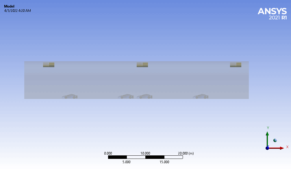
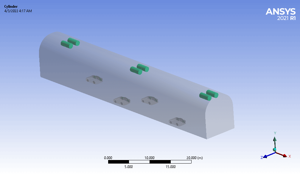
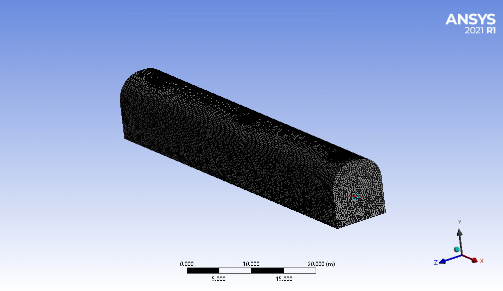
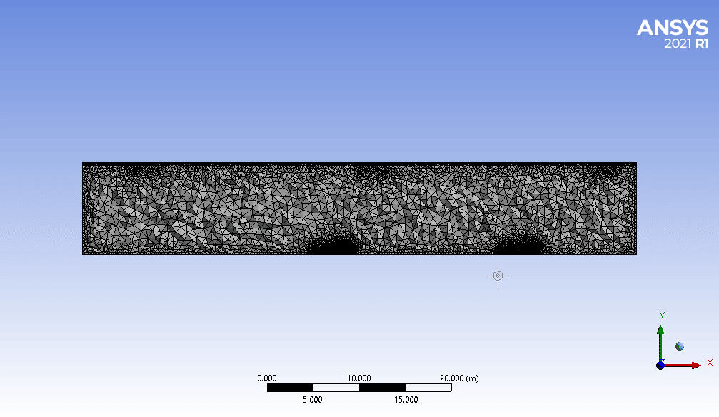
The geometry of the solution is a 3D rectangular domain whose length in X and Y and the Z direction is 60m and 10m and 9m, respectively.
Also, there are four cars in different locations of the tunnel. There are three pairs of fans on top of the tunnel at a distance of 25 m.
Design Modeler software is used to create the geometry of the solution.
ANSYS Meshing software is used for generating meshes of the solution. The elements are all tetrahedra. After importing the mesh into the fluent software, the elements are changed to polyhedral because their number decreases significantly.
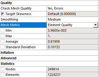
The number of the elements is precisely 1224231:
The charts below show the quality of the elements.
The elements’ minimum, maximum, and average quality are 5.96e-3, 1, and 0.8190, respectively.
Smoke Ventilation Using Jet Fan CFD Simulation
We consider several assumptions to simulate the present model:
- We perform a pressure-based solver.
- The energy equation is on.
- The present model is steady.
- The effect of gravity is considered.
The following table represents a summary of the defining steps of the problem and its solution:
| Material Properties | |
| Name (Fluid) | air |
| Pollution | |
| density | 0.95 |
| conductivity | 0.0454 |
| Heat capacity | 1100 |
| viscosity | 1.72e-5 |
| Boundary Condition | |
| Type | Amount (units) |
| Pressure-Outlet | |
| Outlet side 1 & Outlet side 2 | gauge pressure = 0 pa |
| wall | |
| Tunnel wall & Street & cars | No-slip |
| Cell Zone Conditions | ||||
| Fan 1&2&3&4&5&6 | 3D Mesh Zone | |||
| Rotational Velocity | 240 rpm | |||
| Models | ||||
| Energy | on | |||
| Turbulence models | ||||
| viscous model | K-epsilon | |||
| K-Omega model | Standard | |||
| Near wall treatment | Standard wall function | |||
| Solution methods | ||
| Coupled | pressure velocity coupling | |
| Second-order upwind | pressure | spatial discretization |
| First-order upwind | momentum | |
| First-order upwind | turbulent kinetic energy | |
| First-order upwind | Specific dissipation rate | |
| Second-order upwind | energy | |
| First-order upwind | Pollution fraction | |
| Initialization | ||
| standard | initialization method | |
| 0 (Pa) | gauge pressure | |
| 0 (m/s) | y-velocity | |
| 0 (m/s) | x-velocity | |
| 0 (m/s) | z-velocity | |
| Run calculation | ||
| Number of Iterations | 400 |
Smoke Ventilation Using Jet Fan Results & Discussion
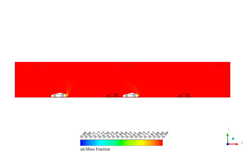
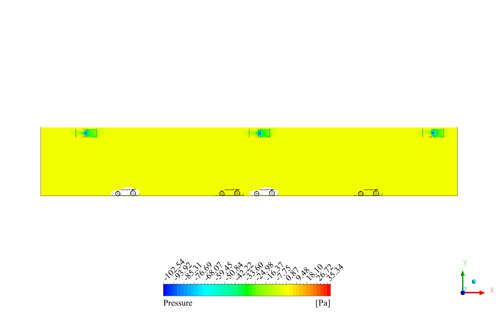
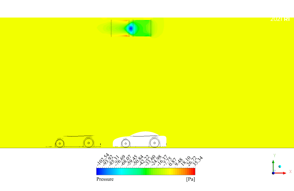
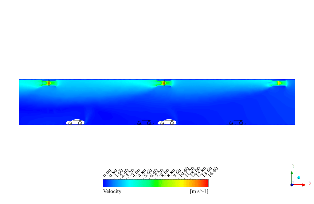
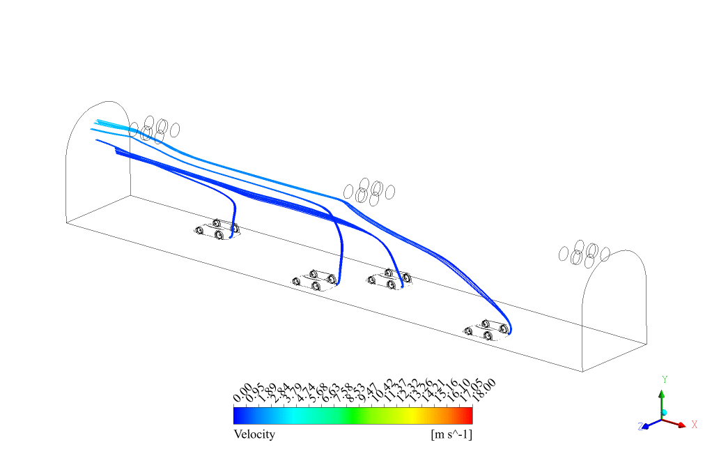
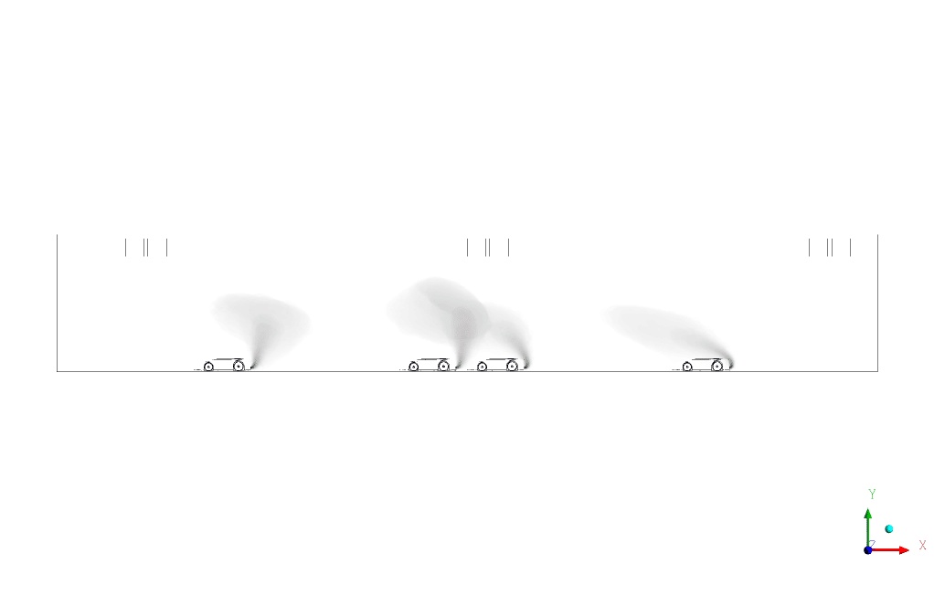
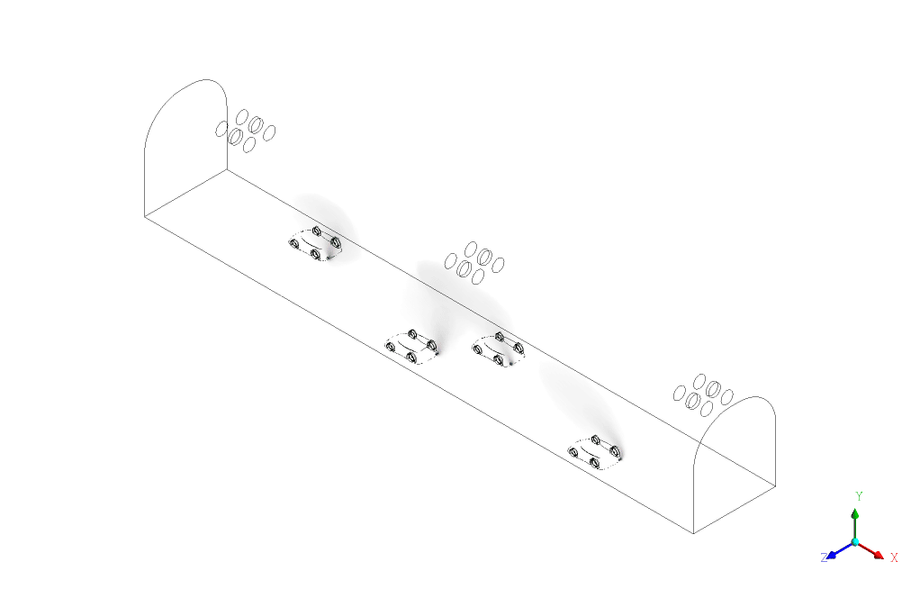
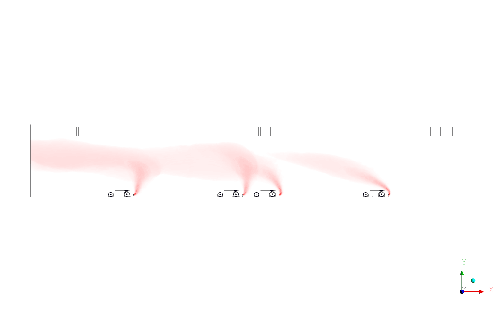
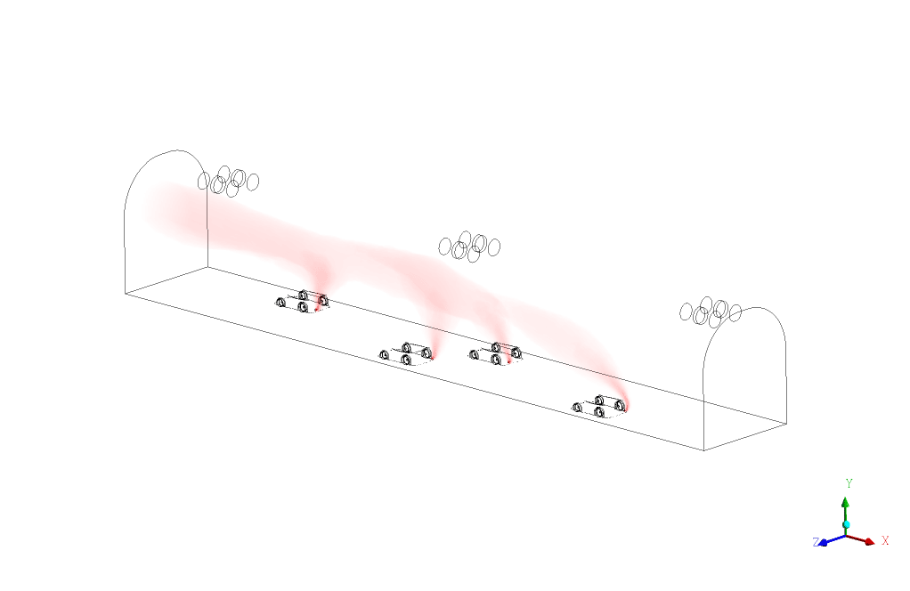
At the end of the solution process, two-dimensional contours of pressure, velocity, and volume fractions of pollution and air are obtained. Also, the contours are visible at every five iterations.
The static pressure is visible at different tunnel parts caused by fans.
It also streamlines the pollution blowing out of the exhaust and shows the exact trajectory through the fans.


Miss Holly Quitzon MD –
How effective did the jet fans demonstrate their ability to control smoke in the tunnel simulation?
MR CFD Support –
The simulation demonstrates that jet fans are effective in controlling smoke in a tunnel environment. The provided results from the simulation, including two-dimensional contours of pressure and velocity, indicate that the implemented ventilation strategy can successfully disperse and evacuate smoke produced by a fire or the exhaust of vehicles.
Chelsey Stehr –
The detailed simulation results were very insightful. It’s apparent that a lot of work went into making sure the jet fans effectively control smoke and pollution in the tunnel. Great job in visual representation and clear explanation of methods and setup.
MR CFD Support –
Thank you for your kind words! We’re glad to hear that you found the simulation results insightful and that the visual representations, along with the methodical explanations, were clear and helpful. If there’s anything more you’d like to know or discuss, we’re here for you!
Arjun Connelly –
I’m wondering if the simulation accounts for varying car speeds and how this might affect the smoke dispersion and extraction effectiveness?
MR CFD Support –
In this simulation, we do not vary the car speeds; we assume a constant speed for the cars to assess the general effectiveness of the smoke ventilation system with jet fans. Factors such as varying car speeds would affect the real-life deployment of such systems, but for modeling purposes, we ensure controlled conditions to study the baseline behaviors of smoke dispersion and fan extraction.
Dr. Gretchen Ruecker –
I was impressed by the detail in the Smoke Ventilation Using Jet Fan simulation tutorial. However, could you please clarify how the pollution is specifically being modeled and tracked within the system?
MR CFD Support –
In the Smoke Ventilation Using Jet Fan simulation, pollution is modeled using a separate material with its specific properties such as density, conductivity, heat capacity, and viscosity. It’s tracked as a distinct variable within the fluid flow and is measured in terms of volume fraction contours, which represent the concentration and distribution of the pollution throughout the tunnel. This allows us to visualize how effective the jet fans are in removing the pollution.
Dr. Freda Hirthe MD –
The polyhedral mesh has really changed my perspective on meshing quality and element count! Does converting tetrahedra to polyhedra typically lead to lower computational costs without sacrificing accuracy?
MR CFD Support –
Absolutely, converting tetrahedral meshes to polyhedral leads to reduced computational costs since polyhedral meshes have fewer elements, which makes calculations faster. Moreover, due to their geometry, polyhedral cells capture the physics of a flow better and can enhance solution accuracy, especially in complex flows.
Alphonso Heaney –
I was impressed with how the Smoke Ventilation Using Jet Fan CFD Simulation tackled various technical challenges. The results were presented in a clear and understandable way, which for me is critical when learning about complex flow dynamics in tunnels. It’s enlightening to see the pollution extraction process being simulated so realistically.
MR CFD Support –
Thank you for your kind words! We’re thrilled to hear that the Smoke Ventilation Using Jet Fan CFD Simulation has met your expectations and provided a clear understanding of complex flow dynamics within tunnel environments. Educating and empowering our users is what drives us, and we’re glad you found the results to be presented in a digestible manner. Thank you for trusting MR CFD for your learning journey, and we look forward to providing you with more high-quality simulations and educational content!
Nash Runolfsdottir PhD –
This training seems quite versatile. Was the simulation able to account for different levels of traffic density and various emergency scenarios, like different sized fires or accidents, during the testing of the smoke ventilation system?
MR CFD Support –
The training you’re referring to focuses primarily on demonstrating the functionality of jet fans in a tunnel during typical conditions, such as car exhaust and potential fire scenarios. While this specific simulation might not cover varying traffic densities or a wide range of emergency scenarios, modifications and new simulations can indeed be conducted to investigate these factors. Interested customers, however, are encouraged to consult MR CFD for further tailored simulations matching specific conditions or events like varying traffic densities and more complex fire scenarios.
Mikel Mann –
I used the training material for this simulation, and found it excellent for visualizing airflow in complex environments like tunnels. I’m impressed with how well the tutorial explained the setup for the jet fan-induced airflow.
MR CFD Support –
Thank you for your positive feedback! We’re glad to hear that our training material met your expectations and helped you clearly understand the scenario. We’re always here to provide support and high-quality learning products, so feel free to reach out if you have any more questions or need further assistance!
August Ward IV –
I am impressed by the detail fidelity of your smoke simulation, especially how it follows the airflow through the tunnel. How effectively do the fans evacuate smoke under emergency fire conditions? Is the performance of the smoke release assessed under different fire scenarios in this training material?
MR CFD Support –
Thank you for the positive feedback on our tunnel smoke simulation training. The efficiency of the jet fans in evacuating smoke is thoroughly evaluated in the simulation under standard conditions. However, this module does not incorporate varied fire scenarios. For more specific assessments under varying emergency conditions, reviewing additional training material or conducting custom simulations would be recommended.
Juliet McDermott –
The simulation results and description are impressive. It seems to cover all details I was curious about!
MR CFD Support –
Thank you for your positive feedback! We are thrilled to hear you found the simulation details comprehensive. Do not hesitate to get in touch with us if you need further information or assistance.
Eudora Medhurst –
Is there any specific reason for choosing polyhedral mesh elements over tetrahedral ones after importing into ANSYS Fluent?
MR CFD Support –
The reason for choosing polyhedral mesh elements over tetrahedral ones is that polyhedral meshes can offer better numerical stability and accuracy with fewer cells compared to tetrahedral meshes. This usually leads to a reduction in computational cost and time, while still accurately capturing the fluid dynamics necessary for the simulation of smoke ventilation in a tunnel.
Prof. Saul Shanahan –
The attention to detail in the mesh quality and simulation setup is impressive in the Smoke Ventilation Using Jet Fan tutorial. The clear explanation of the steps from the geometry creation to the solution interpretation provides a solid understanding of the process. The inclusion of fans and vehicles in the tunnel model adds practical scenarios to the simulation, enhancing the learning experience.
MR CFD Support –
Thank you for the great feedback! We strive to offer the most comprehensive and detailed CFD training products. We’re delighted to hear that the clarity and attention to detail in our Smoke Ventilation Using Jet Fan tutorial met your expectations. If you ever have more questions about our products or need further clarification, feel free to reach out. Your understanding and learning experience are our top priority!