Helical Heat Exchanger CFD Simulation, ANSYS Fluent Training
$80.00 Student Discount
This project investigates the heat transfer inside a helical heat exchanger.
Click on Add To Cart and obtain the Geometry file, Mesh file, and a Comprehensive ANSYS Fluent Training Video.To Order Your Project or benefit from a CFD consultation, contact our experts via email ([email protected]), online support tab, or WhatsApp at +44 7443 197273.
There are some Free Products to check our service quality.
If you want the training video in another language instead of English, ask it via [email protected] after you buy the product.
Description
Introduction
A heat exchanger is a system used to transfer heat between two or more fluids. Heat exchangers are used in both cooling and heating processes. The fluids may be separated by a solid wall to prevent mixing, or they may be in direct contact. They are widely used in space heating, refrigeration, air conditioning, power stations, chemical plants, petrochemical plants, petroleum refineries, natural-gas processing, and sewage treatment. The classic example of a heat exchanger is found in an internal combustion engine in which a circulating fluid known as engine coolant flows through radiator coils, and air flows past the coils, which cools the coolant and heats the incoming air. Another example is the heat sink, which is a passive heat exchanger that transfers the heat generated by an electronic or mechanical device to a fluid medium, often air or a liquid coolant.
Helical Heat Exchanger Project description
In this project, the heat transfer inside a helical heat exchanger is investigated by ANSYS Fluent software. The helical heat exchanger consists of a number of coils (helical tubes) with a helix curve (similar to a spring) that are embedded in a shell. To increase the heat transfer level, several pipes are placed in a spiral format next to each other, and all are connected to one inlet and outlet. Numerous experimental studies have been performed on helical tubes’ flow and heat transfer characteristics. The energy equation is activated to obtain temperature distribution inside the computational domain. The standard k-epsilon model is exploited to solve turbulent flow equations. It should be noted that the ideal gas model has been used to determine the density changes in proportion to temperature.
Helical Heat Exchanger Geometry & Mesh
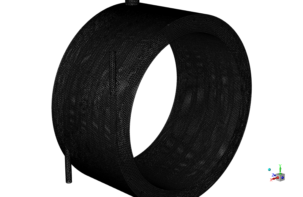
The geometry of this project is designed in CATIA and meshed in GAMBIT. The mesh type used for this geometry is unstructured, and the element number is 890710.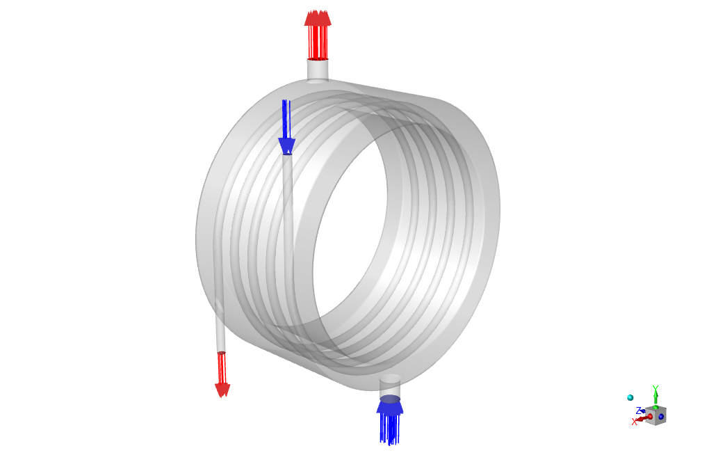
CFD simulation settings
The critical assumptions considered in this project are:
- The simulation uses a pressure-based solver.
- The present simulation’s results are steady and do not change as a function of time.
- We ignore the effect of gravity.
The applied settings are summarized in the following table.
| Models | ||
| Viscous model | k-epsilon | |
| k-epsilon model | standard | |
| near wall treatment | standard wall function | |
| Energy | on | |
| Boundary conditions | ||
| Inlet | Velocity inlet | |
| Inlet2 | 5 m/s | |
| Temperature | 340 K | |
| Inlet-2 | 5m/s | |
| Temperature | 300 K | |
| Outlet | Pressure outlet | |
| Gauge pressure | 0 Pa | |
| Walls | Stationary wall | |
| wall | Heat flux | 0 W/m2 |
| wall.5 | Thermal condition | coupled |
| Solution Methods | ||
| Pressure-velocity coupling | coupled | |
| Spatial discretization | Pressure | PRESTO! |
| Momentum | first-order upwind | |
| Energy | first-order upwind | |
| turbulent kinetic energy | first-order upwind | |
| turbulent dissipation rate | first-order upwind | |
| Initialization | ||
| Initialization method | Standard | |
| gauge pressure | 0 Pa | |
| Velocity (x,y,z) | (0,0,0) m/s | |
| temperature | 334.3642K | |
| Turbulent kinetic energy | 0.09375 m2/s2 | |
| Turbulent dissipation rate | 78.72302 m2/s3 | |
Results
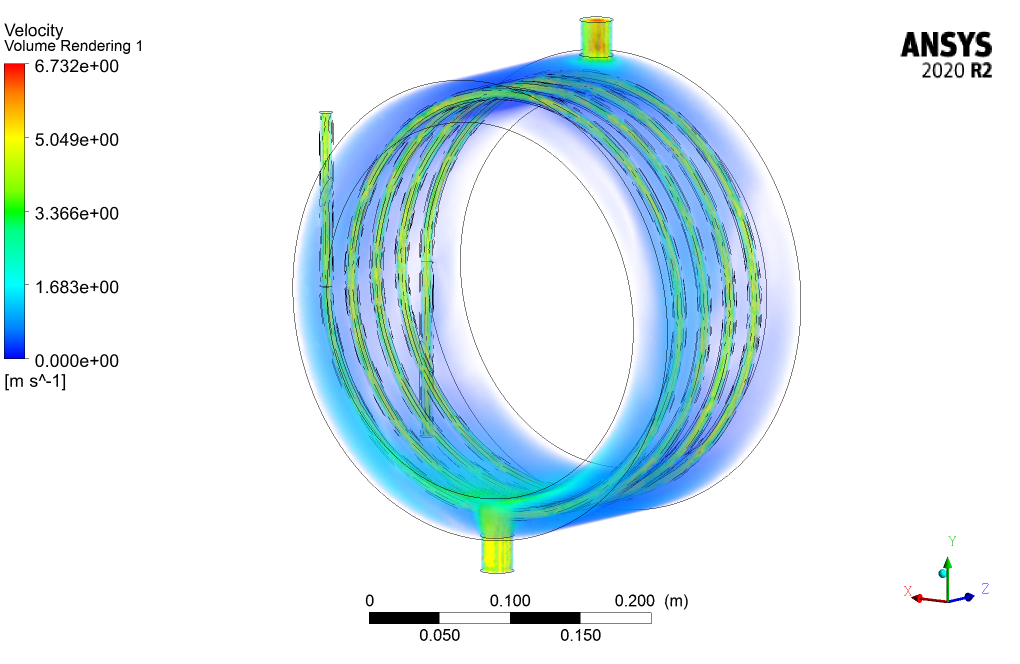
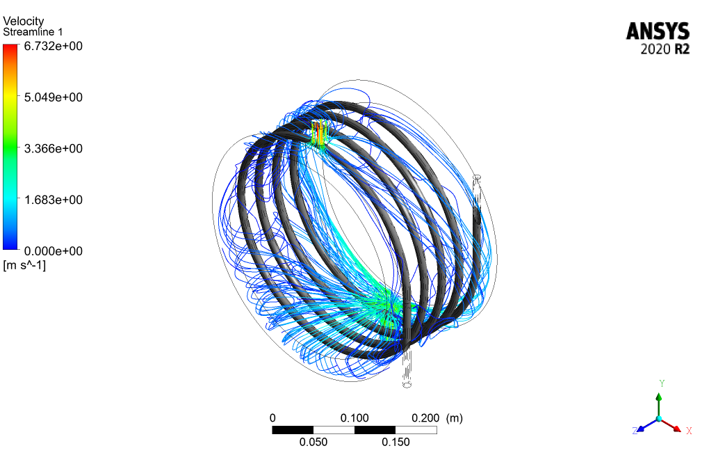
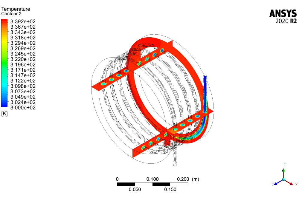
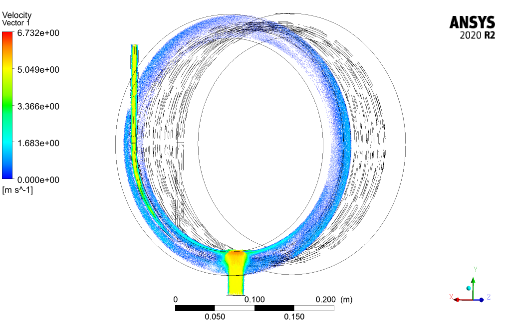
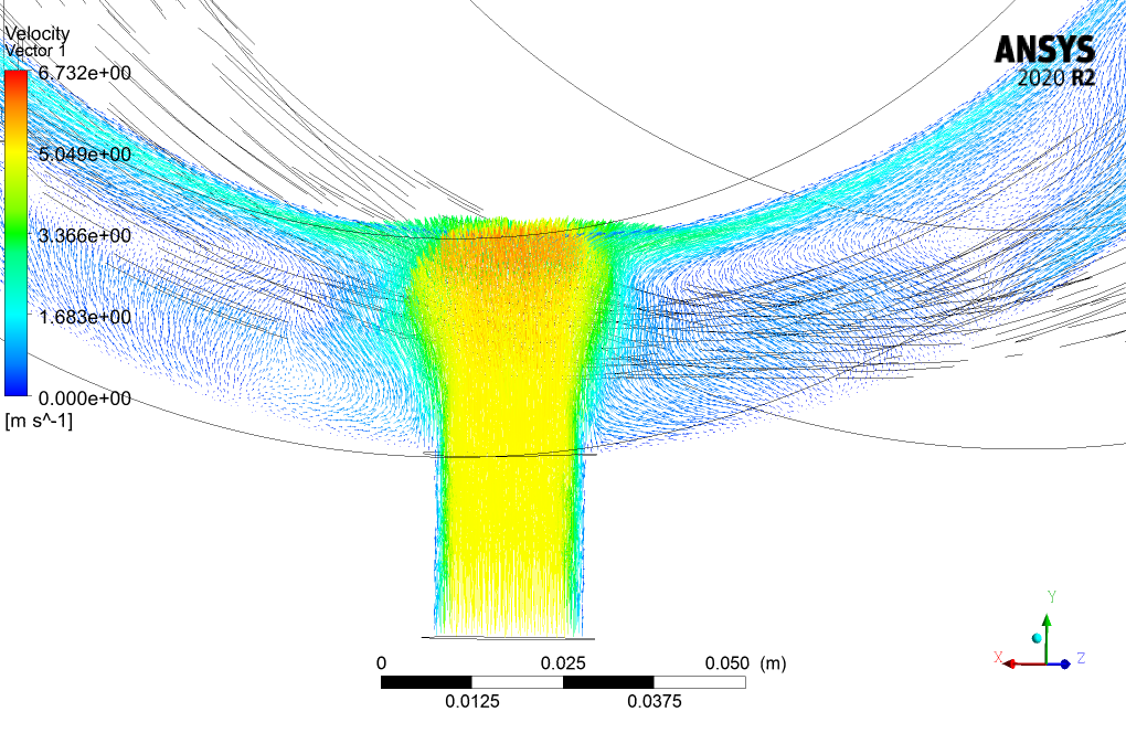
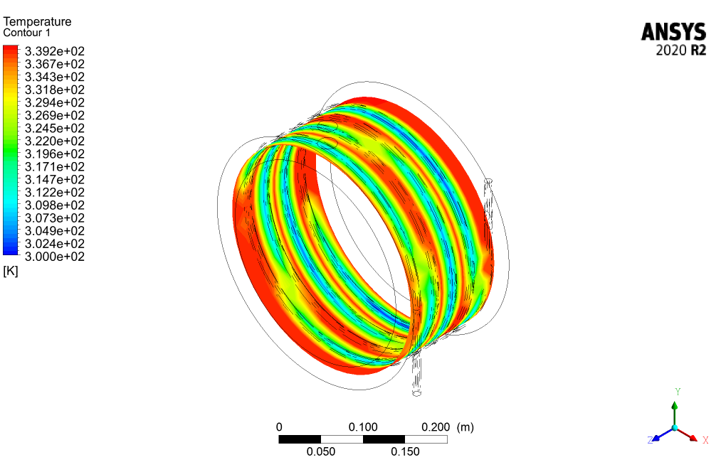
We obtain and present the contours of velocity, temperature, etc., in 3D and 2D.


Miss Jermaine Miller V –
The project description was enlightening! Everything was made clear, and it seems like a comprehensive coverage of the helical heat exchanger simulation was given. The details on the assumptions, geometry, meshing, and boundary conditions all painted a vivid picture of how the simulation was conducted and what factors were considered critical. Well done on this!
MR CFD Support –
Thank you for your positive feedback! We’re thrilled to hear that the project description provided the clarity and comprehensive details you were looking for. If you ever have any more questions or need further information about our simulation projects, feel free to reach out. Your appreciation motivates us to continue delivering high-quality learning materials.
Ludie Rogahn –
This training module seems wonderfully comprehensive! The inclusion of intricate geometry design in CATIA, unstructured mesh generation in GAMBIT, and the use of ANSYS Fluent for simulating a helical heat exchanger’s heat transfer processes is quite impressive. Understanding the interaction of turbulent flow and thermal dynamics in such complex structures is invaluable for any aspiring CFD engineer.
MR CFD Support –
Thank you for your positive feedback! We’re glad to hear that our Helical Heat Exchanger CFD Simulation training has been comprehensive and valuable to your learning experience. Our goal is to provide detailed and applicable knowledge for practical scenarios. If you have any further questions or need more information on our training modules, feel free to reach out!
Russ Von DVM –
Your helical heat exchanger project simulation on ANSYS Fluent really piqued my interest. The explanation about the spiral tubes and the way you use the turbulent flow equations is exemplary. Also, the idea of using the ideal gas model for density changes is innovative. I appreciate the thoroughness in explaining the boundary conditions and solver settings, which provides a clear understanding of your simulation approach.
MR CFD Support –
Thank you so much for your kind words! We’re delighted to hear that you found the project simulation engaging and informative. We always strive to provide comprehensive explanations and realistic setups in our simulations to ensure a deep understanding for users like you. Your appreciation motivates us to keep improving and offering high-quality simulation trainings and tutorials. Thank you for choosing our ANSYS Fluent training for your learning needs!
Dr. Imani Hahn –
Very informative and detail-oriented training for the Helical Heat Exchanger CFD Simulation. The structured steps and clear illustrations enhanced my understanding and application skills. The inclusion of GAMBIT for meshing brought a well-rounded experience to mesh generation techniques.
MR CFD Support –
Thank you for your positive feedback! We are thrilled to hear that our Helical Heat Exchanger CFD Simulation training was helpful to you. Your understanding and successful application of the skills learned during the training are our ultimate goals. Keep up the good work, and we look forward to providing you with more valuable learning experiences!
Prof. Stewart Kautzer –
What model adjustments are required if I want to simulate a transient response in the helical heat exchanger instead of a steady state?
MR CFD Support –
To simulate a transient response, you’ll need to switch from the steady solver to the transient solver in ANSYS Fluent. Additionally, you’d have to adjust your initial conditions and set appropriate time step sizes and total simulation time to capture the dynamic behavior of the heat exchange process. It’s important to ensure that your mesh can resolve the flow features over time, and you may need to activate transient models for turbulence if the flow features change rapidly.
Betsy Schmidt –
The Helical Heat Exchanger CFD Simulation project seems impressive! It looks like extensive research has been done to ensure that this simulation is both accurate and educational.
MR CFD Support –
Thank you for your positive feedback on the Helical Heat Exchanger CFD Simulation! We’re glad you found the project impressive and educational. Our team strives to maintain accuracy and provide valuable insights, and we’re pleased to know we’ve met that goal. Thank you for choosing our ANSYS Fluent training material.