
Liam F1 Wind Turbine CFD Simulation by ANSYS Fluent
$140.00 Internship
- The problem numerically simulates the airflow field adjacent to Liam F1 Wind Turbine using ANSYS Fluent software.
- We design the 3-D model by the Design Modeler software.
- We Mesh the model by ANSYS Meshing software, and the element number equals 1249235.
- We perform this simulation as unsteady (Transient).
- We use the Frame Motion to define the rotational motion of the wind turbine.
To Order Your Project or benefit from a CFD consultation, contact our experts via email (info@mr-cfd.com), online support tab, or WhatsApp at +44 7443 197273.
There are some Free Products to check our service quality.
If you want the training video in another language instead of English, ask it via info@mr-cfd.com after you buy the product.
Description
Liam F1 Wind Turbine, ANSYS Fluent CFD Simulation Training
This project studies Liam F1 Wind Turbine CFD Simulation using ANSYS Fluent software. We perform this CFD project and investigate it by CFD analysis.
Currently, the most-efficient wind turbine designs are not particularly suited for residential installation. They require enough height to catch the wind to be of any use, and then there are noise complaints. Also, bird strikes could be a cause for concern, similar to large-scale wind farms.
Scaling down wind turbines does not help with these problems, so residential systems remain an oddity.
However, recently, an entirely new small-scale wind turbine design named Liam-F1 Urban Wind Turbine can operate at approximately 80% of the Betz Limit, or 47.4% overall efficiency, which states that the theoretical maximum efficiency of any wind turbine is only 59.3%.
Commercial wind turbines max out at 50% of the Betz Limit or just 29.7% efficiency. Due to these unique attributes, in this study, CFD has been employed to evaluate this type of turbine evaluation in an arbitrary wind tunnel situation.
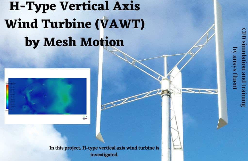
The present model is designed in three dimensions using the Design Modeler software. The geometry included a rotary zone for the turbine walls and a stationary zone for the rest of the domain.
The meshing of the model was done using ANSYS Meshing software. Also, 5 prism layers were added adjacent to the wind tunnel walls and the turbine’s body to calculate the boundary layer accurately. The element number is equal to 1249235.
Also, due to the nature of the present problem, the transient solver has been enabled.
Liam F1 Methodology
By assuming an isothermal, incompressible, and steady-state condition for the air around the blades, two forces are known as the Coriolis, and centripetal accelerations are the important source terms that are exerting on the flow elements.
Briefly, the governing mass and momentum equations are written as follows:
Moreover, the frame motion technique has been used to model the rotating motion of the turbine. Using this technique, there is no need to define an interface between the stationary and rotating domains.
This technique stimulates the turbine motion by rotating the flow within the rotating domain, reducing the computational cost of modeling such problems. The rotating domain rotates with a rotational velocity of 300 RPM.
Furthermore, the flow field is fully turbulent. Thus, we select the k-w-SST turbulent model for the evaluation of eddies.
The noted model has been more accurate than any other eddy-viscosity variation due to a hybrid formulation that takes care of both wall effects and the core flow strain rate. The air enters the domain with a velocity of 3m/s and passes over the designed turbine.
Liam F1 Conclusion
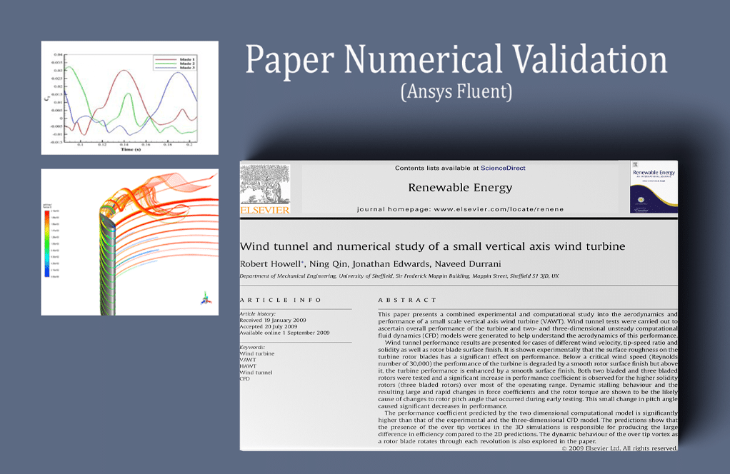
At the end of the solution process, two and three-dimensional contours related to velocity, pressure, and streamlines are obtained.
As shown in the pressure contour over the turbine blades’ surfaces, the turbine wall’s leading edge suffers from the highest-pressure gradient, which is logical since the velocity has just met zero.
We present contour and streamlines for the velocity field to give insight into the problem. Briefly, the velocity field adjacent to the turbine’s wall has the highest gradient, and the wake that arises from it stretches far behind the bird’s body. This could be, again, observed through the velocity vectors.
Additionally, the streamlines vectors illustrate the quality of the flow streams resolved in the wake section, depicted in Figure, which is the core challenge of aerodynamic simulation. Finally, we calculate the drag force 0.14 (N), which is accurate for a turbine with the noted specifications.
Reviews
You must be logged in to post a review.

Freddie Hane III –
I absolutely love the concept of the Liam F1 Wind Turbine and its efficient design for residential areas. It’s promising to hear about the high level of detailed analysis provided by the ANSYS Fluent simulation, especially concerning its potential for quiet operation and fewer bird strikes. Excellent job!
MR CFD Support –
Thank you very much for your kind words and enthusiasm about the Liam F1 Wind Turbine CFD simulation project. It’s always rewarding to see such positive feedback, and we’re grateful for customers like you taking the time to share your experience. We strive to provide detailed and comprehensive simulations, and we’re glad to hear that you appreciate the efforts made for urban sustainability and efficiency. If you have any further inquiries or requires more information about our simulations, please feel free to reach out.
Nathanael Medhurst –
I’m amazed by the efficiency of the Liam F1 Turbine in your study. Can you say more about how it remains efficient in low wind conditions?
MR CFD Support –
Thank you for your positive review. In low wind conditions, the Liam F1 Wind Turbine maintains its efficiency through its unique design. Unlike traditional wind turbines, the Liam F1 is optimized for urban environments where wind directions frequently change and overall wind speed is lower. The blades are designed to leverage the wind from all angles, which allows for effective energy production even in less-than-ideal conditions. Additionally, the specific aerodynamic design minimizes drag and maximizes lift to utilize every gust of wind efficiently, hence maintaining a good level of efficiency even at low wind speeds.
Keenan Dietrich –
This Liam F1 wind turbine simulation seems fascinating! Can you describe how the flow behavior changes as it passes through and beyond the turbine?
MR CFD Support –
Thank you for your interest in the Liam F1 wind turbine CFD simulation training. As air flows through and interacts with the turbine, a high-pressure gradient occurs at the leading edge of the turbine blades due to the sudden deceleration and redirection of the wind flow. This pressure acts to turn the blades, harnessing the wind’s kinetic energy. Downstream of the blades, the velocity decreases, creating a wake characterized by a region of lower velocity and higher turbulence due to the energy transfer to the turbine. The velocity vectors reveal a clear wake stretching behind the turbine, and the streamlines depict the airflow path around the turbine blades, reflecting how effectively the turbine can extract energy from the wind.
Pansy Greenholt –
The project was informative and the simulation very well done. The results helped me understand the efficiency of the Liam F1 wind turbine in urban settings.
MR CFD Support –
Thank you so much for your positive feedback! We’re delighted to hear that our simulation was able to help you better understand the effectiveness of the Liam F1 wind turbine in a residential environment. If there’s any other way we can assist you or any other aspect of our products you’re curious about, don’t hesitate to reach out!
Shanelle Lakin –
The description of applied methodologies is thorough, but I’m curious about the noise levels. Were noise emissions from the Liam F1 Wind Turbine analyzed during the CFD simulation?
MR CFD Support –
In this CFD analysis, noise emissions were not directly studied. The focus was on aerodynamic performance including pressure distribution, flow velocity, and wake characteristics. Noise analysis could potentially be included in a more comprehensive study or via an additional acoustic simulation.
Maurine King –
I’m impressed with the simulation’s attention to detail, especially the use of the k-w-SST turbulent model. Can you clarify whether the drag force you mentioned is within the expected range for a turbine like the Liam F1, and how it compares in terms of efficiency to larger turbines?
MR CFD Support –
Thank you for your interest in our Liam F1 Wind Turbine CFD simulation. The drag force of 0.14 N is within the expected range for this small-scale residential turbine. Small-scale turbines like the Liam F1 are the efficient choice for residential areas. While they cannot match the power output of larger turbines, they operate with considerable efficiency, closer to the Betz Limit, and are well-suited for urban environments. Larger commercial wind turbines have higher power outputs but do face limitations such as lower operational efficiency and are challenged by environmental factors like noise and impact on wildlife.
Mercedes Langworth –
Thank you for introducing a fascinating approach to urban wind turbines. I was particularly impressed with the promised efficiency in such a compact design. Great job on simulating this!
MR CFD Support –
Thank you for your kind words! We’re thrilled to hear that the simulation of the Liam F1 Urban Wind Turbine impressed you. Your positive feedback motivates us to continue delivering high-quality CFD simulation studies and training. If you have any inquiries or need further information, please don’t hesitate to reach out.
Magali Skiles PhD –
The utilization of the k-w-SST turbulence model in this simulation is proficiently portrayed. However, I’m particularly fascinated by how the transitional states between the core flow and wall effects are managed using this hybrid modeling approach. The emphasis on capturing the effects accurately provides a substantial grounding for the computational analysis.
MR CFD Support –
Thank you for your thoughtful compliment on the k-w-SST turbulence model implementation in the Liam F1 Wind Turbine simulation. We strive for accuracy and efficiency in our computational analysis, and it’s gratifying to know that this attention to detail is appreciated by our customers. Your feedback is incredibly valuable as we continue to improve and deliver quality CFD training.
Doyle Balistreri –
The simulation results are fascinating. The pressure gradient across the turbine blades and the detailed velocity fields add so much depth to understanding the aerodynamics involved. Truly remarkable work in capturing the complexity of the wake as well.
MR CFD Support –
Thank you for the positive feedback on the Liam F1 Wind Turbine CFD Simulation! We’re delighted to hear that you found the results fascinating and that you appreciate the detailed analysis of the aerodynamics involved. Your recognition validates the rigorous work our team has put into this simulation, and it encourages us to continue delivering high-quality CFD studies. Feel free to reach out if you need any further information or assistance!
Ariel Welch –
This course significantly improved my grasp of practical CFD applications. It was fascinating to see how residential wind turbine concerns were addressed through simulation, leading to effective predictions of flow patterns around the turbine blades.
MR CFD Support –
We are delighted to hear that our course on Liam F1 Wind Turbine CFD Simulation was beneficial to your understanding of CFD in practical scenarios. It’s great to know that the content helped you appreciate how simulation can overcome challenges in small-scale wind turbine design for residential areas. Thank you for your positive feedback! We look forward to providing you with more educational and insightful courses in the future.
Prof. Eddie Jenkins V –
This CFD analysis provided a comprehensive flow visualization around the Liam F1 wind turbine design!
MR CFD Support –
Thank you for recognizing the effort we’ve put into this analysis to make complex flow visualization comprehensible. We’re really glad to know our work is appreciated and useful to our customers.
Miss Marilou Bahringer –
I recently completed the CFD simulation of the Liam F1 Wind Turbine using ANSYS Fluent based on your training material. I must say, I am genuinely impressed by the level of detail and clarity provided. The simulation confidently mirrored real-world conditions, and I particularly appreciated the explanation of using the k-w-SST turbulent model due to its hybrid formulation for greater accuracy. Thank you for a high-quality learning experience.
MR CFD Support –
Thank you so much for your kind words! We are thrilled to hear that you found our training material for the Liam F1 Wind Turbine simulation to be detailed and clear. Our goal is always to provide a comprehensive learning experience that helps our customers obtain accurate and useful results. Your feedback is greatly appreciated, and we look forward to providing you with more high-quality CFD learning resources in the future.