Centrifugal Compressor ANSYS Fluent CFD Simulation
$80.00 Student Discount
- The problem numerically simulates Centrifugal Compressor with a diffuser using ANSYS Fluent software.
- We design the 3-D model by the Design Modeler software.
- We Mesh the model by ANSYS Meshing software, and the element number equals 303600.
- We use the Frame Motion method to define rotational motion for the centrifugal compressor.
To Order Your Project or benefit from a CFD consultation, contact our experts via email ([email protected]), online support tab, or WhatsApp at +44 7443 197273.
There are some Free Products to check our service quality.
If you want the training video in another language instead of English, ask it via [email protected] after you buy the product.
Description
Centrifugal Compressor ANSYS Fluent CFD Simulation Tutorial
This simulation is about a Centrifugal Compressor ANSYS Fluent CFD Simulation with a diffuser. We perform this CFD project and investigate it by CFD analysis.
One of the most widely used compressors in the industry is the centrifugal type compressor. This compressor uses positive pressure while using centrifugal force to compress the gas. With the compressor impellers’ rotation, low-pressure air is sucked from the central axis and its pressure increases.
This compressed air then exits radially from the diffuser section around the compressor. Only one of the blades is modeled to simplify and reduce the computational cost due to the compressor’s symmetrical structure and the geometric similarity of the compressor blades.
Each blade’s geometric model consists of an in block (connected to input) and a passage (connected to output). Two covers, called hub and shroud, are placed on either side of each blade; So that the blades are located in the space between the two covers.
The compressor blade rotates around its central axis (z-axis) at a rotational speed of 800 rpm. The cause of the diffuser in the air path leaving each blade is the increase in air pressure. When the fluid exits the central part of the compressor, it has kinetic energy and potential.
Since the amount of pressure changes in the passing fluid is inversely related to the square of the fluid velocity (according to the Bernoulli relation), it should be tried to reduce the compressor blades’ output velocity to increase the amount of outlet fluid pressure.
This increase in pressure helps to increase the working efficiency of the compressor. Therefore, a diffuser is used in the compressor; Because the cross-section of the fluid passage increases, and with increasing the cross-sectional area of the passage, the passage velocity decreases, and finally, as the fluid velocity decreases, the outlet fluid pressure increases.
The present model is designed in two dimensions using Design Modeler software. The model is then meshed by ANSYS Meshing software. The model mesh is unstructured, and 303600 cells have been created.
Centrifugal Compressor Method
In this simulation, the rotational movement must be defined for the fluid around the compressor blade. In cell zone conditions, the Frame Motion method is used to define rotational motion.
This means that it is assumed that the blade, as a boundary, has a rotational movement with a velocity of 0 rpm, and the circumference of the passage (passage) and the wall attached to it (hub) has a rotational velocity in the section frame motion at a speed of 800 rpm.
Centrifugal Compressor Conclusion
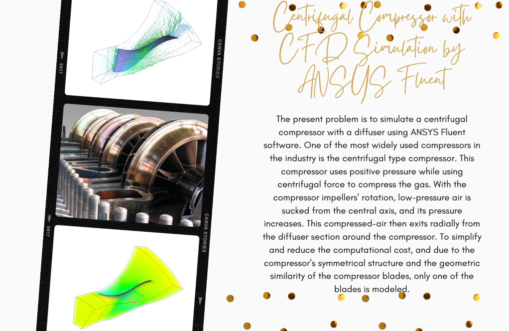
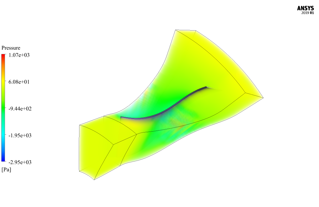
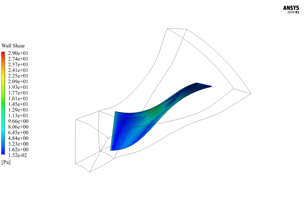
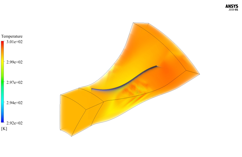
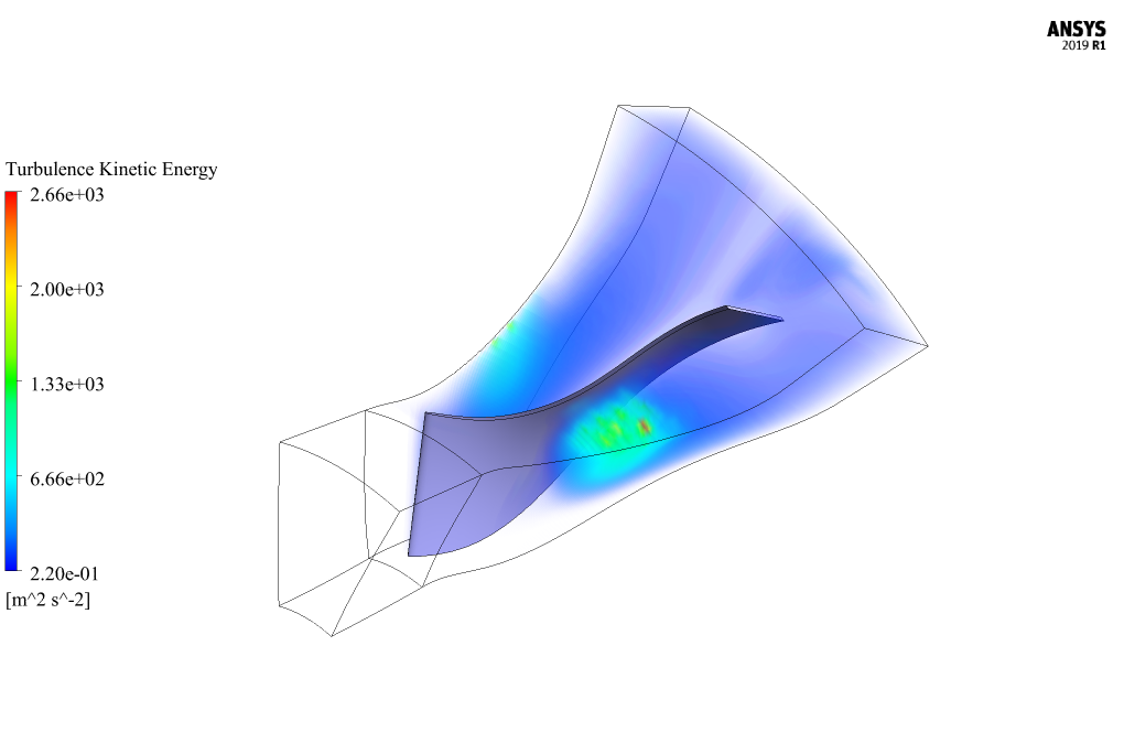
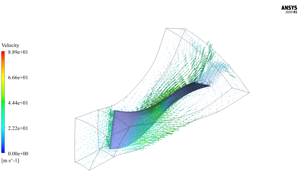
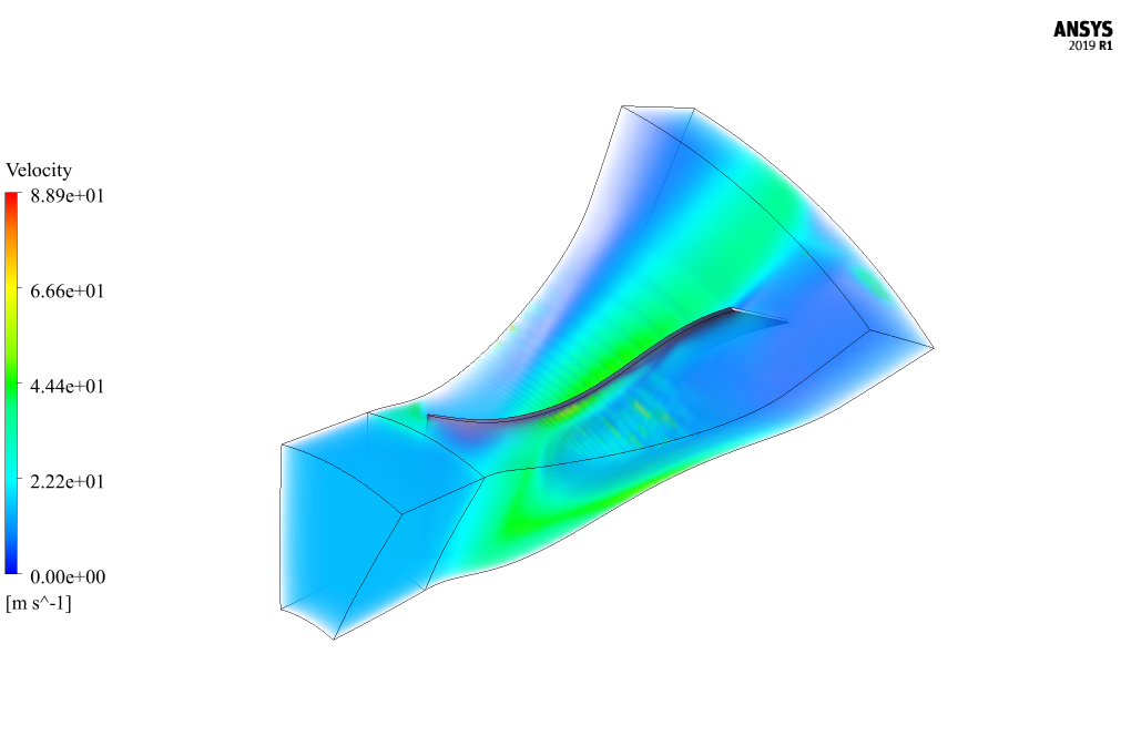
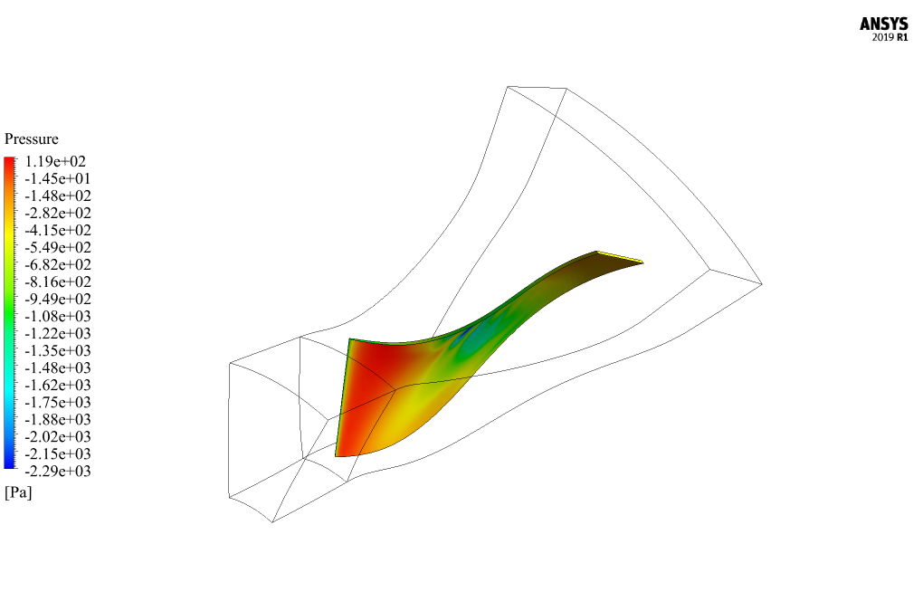
After simulation, two-dimensional contours of pressure and stress are obtained on the compressor blade surface. Three-dimensional contours of pressure, temperature, velocity, and turbulent kinetic energy have been obtained on the compressor blade. 3D velocity vectors have also been obtained.
The fluid’s pathlines clearly show the compressor’s centrifugal nature, as the fluid flow from the central part radially outwards. Also, the changes in pressure and speed around the blade are well shown, which are caused by the rotational movement of the compressor.


Vena Wehner –
I appreciate the dedication to accuracy and validation in this simulation
Prof. Declan Schoen I –
Can this simulation handle compressible and incompressible fluids?
MR CFD Support –
Yes, the simulation can handle both compressible and incompressible fluids. You just need to define the specific properties of the fluid in the simulation setup.
Prof. Erica Hahn –
What are the potential applications of this simulation?
MR CFD Support –
This simulation has a wide range of applications, including but not limited to, HVAC systems, turbochargers, and various industrial processes. It can help in understanding and optimizing these processes.
Bennett Mante –
I really enjoyed the Centrifugal Compressor CFD simulation tutorial. The explanation regarding the impact of diffuser on the air pressure and the way velocity affects the fluid dynamics was enlightening. Understanding the inverse relationship between pressure and velocity squared has deepened my comprehension of the Bernoulli equation in practical applications.
MR CFD Support –
Thank you for your kind words! We’re delighted to hear that you found the tutorial enlightening and helpful in understanding the practical application of the Bernoulli equation in centrifugal compressor simulations. We always strive to provide clear and informative content to aid in learning and comprehension.
Mr. Gregg Morissette –
I am thoroughly impressed with the centrifugal compressor CFD simulation performed on ANSYS Fluent. The inclusion of a diffuser to increase air outlet pressure shows attention to detail and reflects a realistic design commonly used in the industry. Detailed visualization of pressures and flow pathlines greatly augmented my understanding of centrifugal compressors. Looking forward to any advanced tutorial or insights into optimizing compressor efficiency!
MR CFD Support –
Thank you for taking the time to review our centrifugal compressor simulation tutorial. We are glad to hear that the details of our simulation have enhanced your understanding and gave you valuable insights. We continuously aim to help our users with realistic and practical tutorial simulations. Do check back for more advanced materials or get in touch with our team for specific queries on optimizing compressor efficiency.
Sonia Price –
The tutorial on the Centrifugal Compressor ANSYS Fluent CFD Simulation is incredibly detailed and helpful. I followed it closely for my project, and it resulted in a successful analysis. The step-by-step approach made the complex concepts much easier to understand and apply. Thanks for creating such quality content!
MR CFD Support –
We’re thrilled to hear that our Centrifugal Compressor ANSYS Fluent CFD Simulation tutorial was helpful for your project. Thank you for your positive feedback, and we are always here to provide detailed and practical learning materials. We look forward to assisting you with any future CFD learning needs!
Zelma Bruen –
I’m very impressed with the level of detail in the Centrifugal Compressor CFD simulation tutorial. The step-by-step approach really helped me grasp the complexities of modeling and simulating the rotodynamic behavior. Great work!
MR CFD Support –
Thank you for your positive feedback! We’re thrilled to hear that the tutorial was helpful and that you found the detail and approach beneficial for understanding centrifugal compressors. If you have any further questions or need more assistance, feel free to reach out. We’re here to help!
Miss Hosea Ernser –
The clarification on the simulation of the rotational movement in the Centrifugal Compressor ANSYS Fluent CFD is thoughtfully given and makes understanding the complex physical phenomena approachable. Kudos for the mesh detail as well, balancing computational demands while capturing the necessary physics is quite noteworthy. A job well-executed!
MR CFD Support –
Thank you for the kind words and the recognition of efforts to simplify complex simulations in the Centrifugal Compressor ANSYS Fluent CFD project. We strive to provide comprehensive and detailed tutorials to assist users of all levels, and your acknowledgment is highly appreciated.
Eva Pacocha –
I found the breakdown of the diffuser’s role in increasing fluid pressure by reducing velocity very illuminative. It made the concept so much more accessible.
MR CFD Support –
Thank you for your positive feedback! We’re glad to hear that the explanation of the diffuser’s mechanics was clear and helpful. If you have any more questions or need further understanding on any part of the simulation, feel free to let us know!