MHD Effect on Fluid Flow CFD Simulation, ANSYS Fluent Training
$180.00 $90.00 Student Discount
The present problem simulates a fluid flow with electrical conductivity properties in a simple square chamber.
Click on Add To Cart and obtain the Geometry file, Mesh file, and a Comprehensive ANSYS Fluent Training Video.To Order Your Project or benefit from a CFD consultation, contact our experts via email (info@mr-cfd.com), online support tab, or WhatsApp at +44 7443 197273.
There are some Free Products to check our service quality.
If you want the training video in another language instead of English, ask it via info@mr-cfd.com after you buy the product.
Description
MHD Project Description
The present problem simulates a fluid flow with electrical conductivity properties in a simple square chamber by ANSYS Fluent software. The MHD model was used to model this work. Magnetohydrodynamics (MHD) is a science that studies the magnetic properties of electrically conductive fluids. In fact, the MHD deals with the interaction between magnetic particles within a fluid stream and the magnetic field. In this case, the fluid flow field and the magnetic field are combined, which is influenced by the induction of electric current due to the movement of the conductive material in a magnetic field, as well as the Lorentz force due to the interaction of the magnetic field and the electric current.
The MHD model is defined in the present simulation by magnetic induction method. This MHD definition method includes two user-defined scalar magnetic flux field functions in the x and y directions; The electrical potential method, on the other hand, involves a voltage scalar function. For the four boundaries of the computational area of the problem, the boundary condition of the insulating wall type is defined; This means that no electric current is transmitted at these boundaries.
Project Description
This is from the conducting wall boundary condition to define fully conductive boundaries, from the coupled wall boundary condition to define the common boundaries between solid and solid or liquid and solid, and from the wall boundary condition. A thin wall is used to define the boundary condition of limited electrical conductivity. In the present magnetic field simulation, the energy equations, the Lorentz force equations, and the MHD equations are activated, and accordingly, to define the magnetic field in the model, a source term for energy, momentum, and magnetic fluxes are applied.
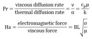
The present problem first examines the dimensionless Prandtl number without applying the MHD model; That is, it examines the ratio of diffusion of motion size to thermal penetration in the model. It then examines the Hartmann number at a constant value of the Prandtl number, followed by the magnitude of the magnetic flux in the presence of MHD; It examines the ratio of electromagnetic force to viscosity force in the model. Finally, at a constant value of the Hartmann number, it examines the changes in the angle of application of the magnetic flux to the fluid flow.
Project Description
To define the desired fluid, from density equal to 998.2 kg.m-3, thermal conductivity equal to 0.6 Wm-1.K-1, dynamic viscosity equal to 0.001003 kg.m-1.s-1, thermal expansion coefficient of 0.000214 K-1, and an electrical conductivity of 1000000 siemense.m-1 (s3.A2.kg-1.m-2) were used. Now, according to the formula for the Prandtl number, the amount of specific heat capacity causes the Prandtl number to change. The value of Prandtl in different models includes 0.01, 0.02, 0.03 and 0.004. Also, according to the Hartmann number formula, the amount of magnetic flux applied causes the Hartmann number to change.
The value of the Hartmann number in different models includes 0.003284, 0.006568, 0.013135, and 0.032838. This value of Hartmann changes with the magnitude of the magnetic flux applied to the model, but this amount of magnetic flux is applied at a certain angle (vertically and only in the direction of the y-axis). In the final part of the work, assuming the amount of magnetic flux is constant, different directions are considered for applying the magnetic field, including an angle of zero degrees (horizontally and only in the direction of the x-axis), an angle of 45 degrees with The x-axis is at an angle of 60 degrees to the x-axis and the 90-degree angle (vertically to the y-axis only).
(MHD)
Geometry & Mesh
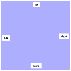
The present 2-D model is drawn using Design Modeler software. The present model consists of a square computing space with a side of one meter, which consists of four walls including up, down, left and right. The following figure shows a view of the geometry.
(MHD)
The meshing of the model has been done using ANSYS Meshing software and the mesh type is structured. The element number is 10000 . The following figure shows the mesh.
MHD CFD Simulation Setting
To simulate the present model, we consider several assumptions:
- We perform a pressure-based solver.
- The simulation is steady.
- The gravity effect on the fluid is not considered.
We present a summary of the defining steps of the problem and its solution in the following table:
| (MHD) | Models | |
| Viscous model | Laminar | |
| Energy | on | |
| (MHD) | Boundary conditions | |
| down wall | Wall | |
| wall motion | stationary wall | |
| temperature | 587 K | |
| left & right | (MHD) | Pressure outlet |
| wall motion | stationary wall | |
| heat flux | 0 W.m-2 | |
| up wall | Wall | |
| wall motion | stationary wall | |
| temperature | 300 K | |
| (MHD) | Solution Methods | |
| Pressure-velocity coupling | SIMPLE | |
| Spatial discretization | pressure | second order |
| momentum | second order upwind | |
| energy | second order upwind | |
| (MHD) | Initialization | |
| Initialization method | Standard | |
| gauge pressure | 0 pascal | |
| temperature | 443.5 K | |
| x-velocity, y-velocity | 0 m.s-1 |
MHD Results
At the end of the solution process, we obtain two-dimensional counters of pressure, velocity, and temperature, as well as two-dimensional pathlines in three different simulation steps. The first step is without applying the MHD model and we compare the Prandtl number and consequently the amount of dynamic viscosity in four different values. The second step is by defining the MHD model and assuming a constant Prandtl number, we compare the value of the Hartmann number and consequently the magnitude of the magnetic flux in four different values but in a fixed direction.
In the third step, by defining the MHD model, assuming the Prandtl number as well as the constant Hartmann number, we compare the direction of applying the magnetic flux in four different angles but with a constant value.






Elliott Schuster –
How does the simulation model the effect of a magnetic field on fluid flow?
MR CFD Support –
The simulation uses the MHD model in ANSYS Fluent to simulate the interaction between the fluid and the magnetic field.
Dr. Osbaldo Leffler –
Can this simulation be used to predict the behavior of a fluid in a magnetic field?
MR CFD Support –
Absolutely! The results from this simulation can provide valuable insights into the behavior of a fluid in a magnetic field.
Rocky Russel –
The use of CFD in this simulation is truly innovative!
Marcus O’Hara –
This MHD simulation seems very complex. I am particularly interested in the impacts of changing the direction of the magnetic flux. Could you briefly explain how altering the angle at which the magnetic flux is applied affects the fluid flow?
MR CFD Support –
Sure, changing the angle of the magnetic flux impacts the fluid flow by altering the direction of the Lorentz force. This influences the flow velocity profile due to changes in the distribution of electromagnetic forces within the flow field, resulting in different flow behavior and heat transfer characteristics.
Mr. Gerardo Champlin Sr. –
The training was excellent. The steps for setting up and executing the MHD CFD simulation were clear, and the user-defined function handling was insightful. Learning about setting proper electromagnetic force conditions and balancing terms like Prandtl and Hartmann numbers provided a solid foundation for further research. Explanations on magnetic field application at varying angles offered a comprehensive understanding of the MHD influence on fluid dynamics.
MR CFD Support –
Thank you so much for your positive feedback! We’re thrilled to hear that our training on MHD CFD simulation has given you a comprehensive grounding in the subject and that it was communicated effectively. Your understanding of intricate concepts like the Prandtl and Hartmann numbers coupled with the user-defined functions will undoubtedly be valuable in your future projects. Should you have any further questions or need advanced guidance, don’t hesitate to ask.
Anita Anderson –
This MHD training has provided a detailed analysis of fluid flow in varying magnetic fields. While the description explained the case and settings well, I’m curious about potential real-world applications of this simulation. How would MHD simulation help in an industrial context?
MR CFD Support –
In real-world industrial applications, MHD simulation can play a crucial role in designing and optimizing systems where electromagnetic fields interact with electrically conductive fluids. Some examples include the development of magnetic drug targeting in medical fields, improving the efficiency of liquid metal cooling in nuclear reactors, and advancing the performance of electromagnetic pumps used in metallurgy. Such simulations help in predicting the behavior of the conductive fluid under magnetic influence, optimizing design to minimize energy consumption and increase system safety and reliability.
Ms. Krystel Smitham –
This product description is invaluable for anyone interested in the impact of MHD on fluid flow. Thank you for making this kind of specialized material so approachable and comprehensive.
MR CFD Support –
We’re pleased to know that you found our MHD Effect on Fluid Flow CFD Simulation training helpful and understandable. We are committed to providing high-quality learning materials, and we appreciate your positive feedback. Thank you for taking the time to review our product.
Miss Maymie Osinski –
Does the model take into account the thermoelectric effects due to the MHD interaction, and if so, how is this accomplished within ANSYS Fluent?
MR CFD Support –
In the simulation, the thermoelectric effects caused by the interaction of the magnetic field and the electric current that can lead to temperature variations are considered. This thermoelectric interaction is simulated by combining the magnetic field equations with the energy equations. ANSYS Fluent utilizes source terms for energy, momentum, and magnetic fluxes to simulate these MHD effects. To accurately represent these interactions, temperature-dependent material properties and proper boundary conditions are applied within Fluent’s framework.
Filiberto Schiller –
This simulation is a great tool for predicting the behavior of a fluid in a magnetic field.
Mandy Schinner –
Thank you for this comprehensive course on MHD Effect on Fluid Flow simulation! I learned so much about how magnetohydrodynamics interacts with conductive fluids and appreciated the thorough exploration of Prandtl and Hartmann numbers. Excellent work incorporating such complex phenomena into an accessible training!
MR CFD Support –
Thank you very much for your positive feedback on our MHD Effect on Fluid Flow CFD Simulation course. We’re delighted to hear that you were able to gain deep insights into the subject, and appreciate your recognition of our efforts to make such complex simulations approachable. Should you have any further questions or wish to enhance your knowledge even more, please don’t hesitate to reach out.
Krystal Corkery I –
The explanations about the Prandtl and Hartmann number variations are quite intriguing. Could you please explain a bit further how the constant Hartmann number affects the flow when the direction of the magnetic flux is changed?
MR CFD Support –
Within the CFD simulation, the Hartmann number is inherently a measure of the relative strength of the electromagnetic force compared to the viscous force within the fluid. Even when the Hartmann number is kept constant, changing the direction of the magnetic flux alters the orientation of the Lorentz force, which can significantly influence the flow structure. At different angles, the magnetic field interacts with the fluid flow and the induced electric current in distinctive ways, leading to diverse patterns of flow circulation and distributions of the velocity, pressure, and temperature fields.
Melyssa Stoltenberg –
The training material on MHD effect on fluid flow in ANSYS Fluent is terrific! The step-by-step approach made it easy for me to understand the complex interplay between electrical currents and magnetic fields on the fluid flow. The inclusion of different numerical values for Prandtl and Hartmann numbers helped in grasping the impact of varying these parameters on the flow characteristics. The supplemental visual aids like two-dimensional contour plots were highly beneficial. I look forward to applying these concepts in my projects.
MR CFD Support –
Thank you for your positive feedback! We are thrilled to hear that our training material on the MHD effect was helpful and provided a clear understanding of the topic. We strive to produce comprehensive educational content and are pleased it enriched your learning experience. If you have any projects that you embark on using this knowledge, we’d love to hear about your experiences in future. Keep exploring and learning! 🌟
Creola Gaylord –
After completing the MHD simulation course, I’ve gotten a very thorough understanding of how magnetic fields interact with conductive fluids. The structured mesh and clear boundary definition made it easier to follow and replicate the simulation on my system. Kudos to the MR CFD team for such detailed work!
MR CFD Support –
We’re delighted to hear about your positive experience with our MHD simulation course. Your understanding of magnetohydrodynamics principles and their applications seems to have deepened through our training. Thank you for your generous compliments, and if you’re ever curious to explore further or need assistance with advanced topics, feel free to reach out. Happy simulating!
Rowland Beatty –
Can you explain how the alteration in the angle of the magnetic field affects the fluid flow?
MR CFD Support –
When the angle of the magnetic field is altered, it changes how the magnetic lines of force interact with the fluid particles. Varying the angle will influence the orientation and magnitude of the Lorentz force, which in turn can affect the velocity profile, pressure distribution, and temperature gradients within the fluid. This simulation investigates such impacts at various angles to provide a comprehensive understanding of the MHD effects on fluid flow.
Cicero Zulauf –
Impressive details and results! The simulation’s approach to varying proves useful for understanding the MHD effects on fluid flow. Your meticulous process, using to model the physical interaction between fluid dynamics and magnetic fields, illustrates a nuanced understanding of electromagnetism within fluids. The structured approach to Prandtl and Hartmann number variation offers clear insight into how these dimensionless numbers influence flow characteristics under different magnetic fields. This seems like a vital study for fields like aerospace and energy where MHD phenomena play a crucial role.
MR CFD Support –
Thank you very much for your kind words! We’re thrilled to know that our Magnetohydrodynamics (MHD) CFD Simulation training provided you with valuable insights into the complex interactions within electrically conductive fluids. We aim to deliver in-depth and practical understanding through our simulations, and we’re glad that the training was not just educational, but also engaging. If you have any further questions or need assistance in future projects, do not hesitate to reach out. We appreciate you taking the time to share such positive feedback!
Ebba Schamberger DDS –
I’ve been curious about how electrical conductivity affects a fluid’s behavior. Does the simulation provide insights into practical applications like cooling systems or energy generation?
MR CFD Support –
The simulation provides essential insights into the impact of electrical conductivity on fluid dynamics, particularly through the Magnetohydrodynamics model. These insights are indeed beneficial for practical applications such as enhancing the performance of cooling systems in electronic devices and optimizing energy generation in MHD generators.