
Discrete Phase Model (DPM) Panel: Interaction, Particle Tracking & Treatment
Introduction
This article investigates the general settings of any DPM simulation located in the Discrete Phase Model dialog box, including interaction, particle tracking and particle treatment.
Interaction
 Panel: Interaction, Particle Tracking &Amp; Treatment 1")
The following figure shows that the first window consists of three main parts: the Interaction part, the Particle Treatment part, and several tabs relating to more details. We will delve into them separately.
 Panel: Interaction, Particle Tracking &Amp; Treatment 2")
DPM Interaction
Its title introduces this section which refers to the assumptions that need to be made for interaction between continuous flow and particles.
- Interaction with Continuous Phase: If we want to consider the mutual influence of particles and continuous flow on each other, we must activate it. This type of simulation is known as two-way coupling.
- Update DPM Sources Every Flow Iteration: In transient simulations, you can see that it is active by default. The DPM sources update after each flow iteration. On the other hand, to update DPM sources after any desired flow iterations, use DPM Iteration Interval. Use larger numbers to simulate the steady state and stability of the solution.
Particle Treatment
- Unsteady Particle Tracking: It is activated by default in transient simulations. The particle tracking equations are solved in unsteady form and the continuous phase.
- Track With Fluid Flow Time Step: By activating this option, the time step size of the discrete phase equals the time step size of the continuous phase. The other choice is to define Particle Time Step Size. In addition, particle injection time can be set at “Inject Particles at.” It should be coordinated with the Particle time step or Fluid flow time step.
Tracking
- Number Of Steps: We can use steady-state simulations to define the maximum number of time steps to follow particles if they remain in the fluid domain. It recommends the higher number results in better convergence, and 500 to 2000.
- Step Length Factor: We can use it to control time step size for the motion of the particles—the more minor value results in higher trajectory accuracy.
Length Scale
 Panel: Interaction, Particle Tracking &Amp; Treatment 3")
This option controls the integration time step size related to the motion equations of the particle. The integration time step size is computed by ANSYS Fluent based on a specified length scale:
 Panel: Interaction, Particle Tracking &Amp; Treatment 4")
The length scale could be defined as the distance a particle travels until its motion equations are solved again. Setting smaller values for the Length Scale will increase the accuracy of the trajectory and vice versa.
Step Length Factor
 Panel: Interaction, Particle Tracking &Amp; Treatment 5")
TheStep Length Factor is equivalent to the time steps required for a particle to travel from the current cell. A more significant value for the Step Length Factor decreases the discrete phase integration time step size.
DPM Problem Approach
Regarding time configuration for solving DPM problems, various parameters control the time of both phases(continuous and discrete phases). Including flow time step size, particle time step size and injecting time step size.
Three approaches could be considered for the mentioned subject:
- Steady particle tracking with steady-state solution
- Unsteady particle tracking with the steady flow
- Unsteady particle tracking with unsteady flow
Steady flow – Steady Particle Tracking
We can use one-way or two-way coupling when using steady simulation along with steady particle tracking. In this approach, a number of iterations for the continuous phase and a DPM iteration interval (N) must be specified. Therefore, after each N continuous phase iteration, DPM sources are updated.
 Panel: Interaction, Particle Tracking &Amp; Treatment 6")
This project, available in learning products of mrcfd.com, investigates the effect of steady-state impurities on splitter erosion.
 Panel: Interaction, Particle Tracking &Amp; Treatment 7")
Steady Flow – Unsteady Particle Tracking
We can use one-way, two-way, or four-way coupling with steady simulation and unsteady particle tracking. In this approach, we must define Particle Time step size. Notice that the injection time is set based on DPM Iteration Interval. For example, as shown below, after every 10 iterations, the particles will be injected and the operation repeats with a 0.001s time step. The number of time steps can also be increased.
Assume that we have defined DPM Iteration Interval: 20, Particle Time step size: 0.005, Number of Time steps:10. Hence, after 20 iterations, particles will be injected 10 times with a 0.005s time interval.
 Panel: Interaction, Particle Tracking &Amp; Treatment 8")
This project, available in learning products of mrcfd.com, investigates the color spraying on the wall with unsteady particle tracking and steady flow.
 Panel: Interaction, Particle Tracking &Amp; Treatment 9")
Unsteady Flow – Unsteady Particle Tracking
When using transient states for both continuous and discrete phases, the same and different time steps could be set for them.
- Same time step sizes for both phases
 Panel: Interaction, Particle Tracking &Amp; Treatment 10")
Discrete phase calculation will occur first, at the beginning of the flow time step, and then every interval specified in DPM Iteration Interval in continuous phase time step iterations. During each DPM calculation, particles advance from their position until the end of the current flow time step, so the number of DPM time steps in a flow time step is equivalent to 1.
- different time step sizes for both phases
Discrete phase calculation will occur first, at the beginning of the flow time step, and then every interval specified in DPM Iteration Interval in continuous phase time step iterations. During each DPM calculation, particles advance from their position until the end of the current flow time step, so the number of DPM time steps in a flow time step is equivalent to Panel: Interaction, Particle Tracking &Amp; Treatment 11") .
.
In the case of injection time, there are two options in the ‘Inject Particles at‘ tab in which Ansys fluent could set Particle Time Step to inject particles at the beginning of particles time step and Fluid Flow Time Step to inject particles at the beginning of continuous phase time step.
 Panel: Interaction, Particle Tracking &Amp; Treatment 12")
This project, available in CFD shop of MR CFD.com, investigates the Corona Virus Dispersion in an Elevator Cabin due to a Sneeze with the Track with Fluid Flow Time-step option.
Corona Virus Dispersion in an Elevator Cabin due to a Sneeze
 Panel: Interaction, Particle Tracking &Amp; Treatment 13")
Related Posts
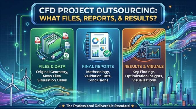
CFD Project Outsourcing: What Files, Reports, and Results Should You Expect?
When engineering teams decide to outsource CFD simulation, the conversation almost always starts with capability and…
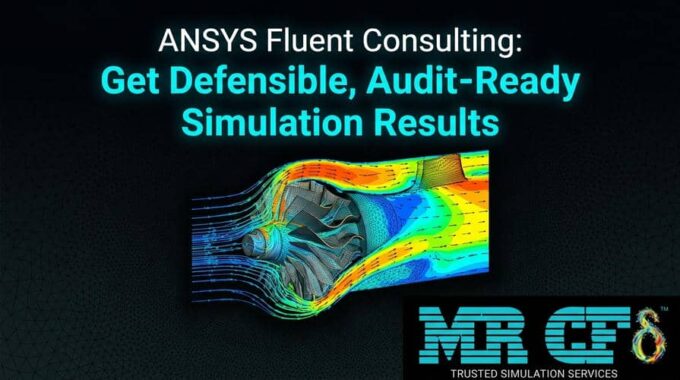
ANSYS Fluent Consulting: Get Defensible, Audit-Ready Simulation Results
You need ANSYS Fluent results that can survive scrutiny — a design review, a client…
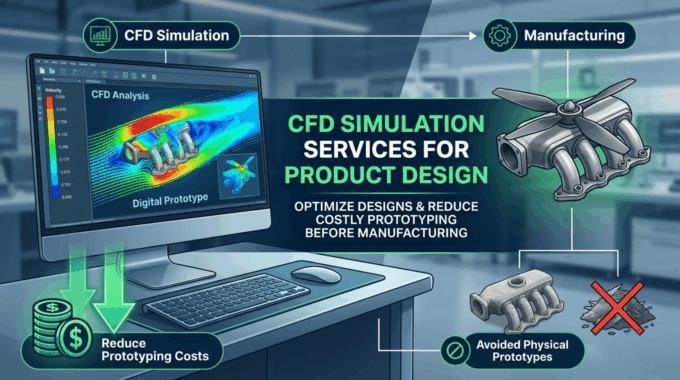
CFD Simulation Services for Product Design: Reduce Prototyping Cost Before Manufacturing
In modern product development, the most expensive mistakes are often discovered after money has already…
Comments (0)