Combustion CFD Simulation Training Package, Beginners, 10 Exercises
$567.00 Student Discount
- Pollutant prediction in the combustion chamber
- Vortex flame combustion chamber
- Gas turbine combustion chamber
- Vortex combustion chamber
- Non-premixed combustion
- Flare system
To Order Your Project or benefit from a CFD consultation, contact our experts via email ([email protected]), online support tab, or WhatsApp at +44 7443 197273.
There are some Free Products to check our service quality.
If you want the training video in another language instead of English, ask it via [email protected] after you buy the product.
Description
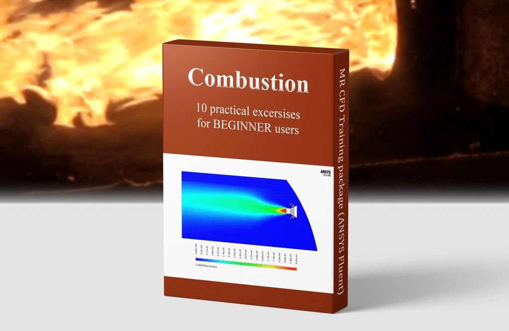
Combustion ANSYS Fluent CFD Simulation Training Package for BEGINNER Users
This training package includes 10 practical Combustion exercises using ANSYS Fluent software. MR CFD suggests this package for BEGINNER users who tends to learn the simulation process of combustion problems without any strong background.
Combustion Chamber
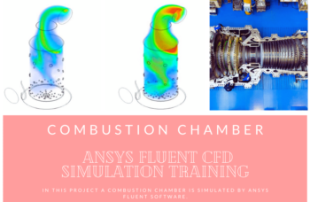
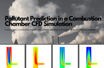
In project number 1, the fundamentals of combustion are presented by simulating a combustion reaction inside a combustion chamber. In a gaseous state, the volatile coal mixture enters the combustion chamber and mixes with high-temperature airflow (1623 K). As a result, the combustion process takes place. This process will also result in different productions, including pollutants like NOx, SOx, etc., which will be analyzed in this project.
Gas Turbine
In project number 2, a two-dimensional combustion simulation in a gas turbine is performed. Methane-air fuel mixture combustion inside a gas turbine combustion chamber is simulated. Methane and oxygen are injected inside the combustion chamber with the velocity of 128.9304m/s and 12.0396m/s and the temperature of 286K and 109K, respectively. The fuel mixture is then ignited, and energy and heat are generated.
Like the previous project, gas turbine combustion is simulated in project number 3, but this time, the simulation is performed in three-dimensional, and diesel fuel is replaced. The fuel used in this process is diesel (C16H29), which reacts with airflow.
Vortex Combustion Chamber
The vortex combustion chamber is a new generation of liquid fuel internal combustion engines in which a whirlpool flow is created with a different arrangement of injectors.
In project number 4, a reaction is simulated inside a vortex combustion chamber. A mixture of air and methane is used as the fuel mixture. The eddy-Dissipation method has been used to investigate the chemical-turbulent interaction of reactants; the NOx anticipation model is activated.
Project number 5 simulates the vortex flame inside a combustion chamber. The airflow enters the chamber in a radial direction from four inlet sections with angles of 90 degrees relative to each other located on the outer circumference of the chamber; While the flow of methane gas as fuel from the other four inlets is sprayed directly into the interior of the chamber.
Non-Premixed
In the non-premixed type, fuel and oxidizer enter the reaction zone of the chamber through separate paths; They do not mix (premix) before fully entering the chamber. In the non-premixed model, the definition of a mixed fraction is used, which represents the mass fraction derived from the fuel flow. In project number 6, Through two separate and independent inlets, airflow (consisting of N2 with a mass fraction of 0.767 and O2 with a mass fraction of 0.233) with a temperature of 300 K and a flow rate of 1.19 kg.s-1 and fuel flow (consisting of CH4 with a mass fraction of 1 At a temperature of 300 K and a flow rate of 0.019 kg.s-1) enter the chamber to combine the chemical reaction of combustion to occur.
Steady-State & Transient Solvers
There are two options to perform a simulation. In steady-state simulations, the variables don`t consider a function of time. In project number 7, a steady-state combustion chamber is simulated. The present chamber has two air inlets. The air of the first inlet hits several blades (to circular the flow) and then enters the chamber. On the other hand, a transient model is required to consider the variable changes over time. In Project number 8, a similar problem is investigated, but the simulation is done in transient form.
Flare System
The flare system, also known as a gas flare, is a combustion device used in industrial units such as oil and gas refineries and oil and gas wells, especially in offshore platforms. Gas flares are responsible for burning the natural gases released during oil extraction in a completely controlled manner. Some natural gas accumulates on top of the oil in the reservoirs during the oil extraction process. Project number 9 simulates combustion in a gas flare system. At the tip of the flare, a gas flow with a flow rate of 0.09259 kg.s-1 enters the environment in the form of a combination of hydrocarbons, and at the same time, a methane flow from the pilot flame at a speed of 2.479 ms-1 to ignite gases as well as water vapor flow enter the environment at a speed of 2.479 ms-1.
In project number 10, a two-step mechanism of combustion in a gas flare in the presence of wind flow is simulated. A mixture of methane and air is burned in a two-step mechanism; they produce a chemical reaction in two consecutive stages. Initially, methane and oxygen react to produce carbon monoxide, and then carbon monoxide combines with oxygen to produce carbon dioxide.


Meaghan Skiles V –
Does the package cover the effect of chemical reactions on combustion behavior?
MR CFD Support –
Yes, indeed. The package includes exercises that delve into the effect of chemical reactions on combustion behavior. This is particularly useful in processes where chemical reactions play a significant role.
Mr. Bernie O’Conner Sr. –
I enjoyed the step-by-step approach of the Combustion CFD Simulation Training Package. It was ideal for a beginner like me, and it helped me understand the complex physics of combustion in a very intuitive way. The range of projects from chambers to gas flares provided a comprehensive learning experience.
MR CFD Support –
Thank you for your positive feedback! We’re thrilled to hear that our step-by-step approach was effective in introducing you to the complexities of combustion simulations. We pride ourselves on creating learning material that is both educational and accessible to beginners. Your understanding and insights will undoubtedly serve you well in future simulations. Keep up the great work!
Mr. Titus Kertzmann –
I’m interested in simulating spray combustion. Does the package cover that?
MR CFD Support –
Sure. The package includes exercises that focus on spray combustion. This is a complex phenomenon that’s crucial in many applications, such as diesel engines and gas turbines.
Dr. Kirstin Schneider –
The course brilliantly lays out the basics of combustion CFD simulation, perfect for a beginner like me. The gradual progression from combustion chamber dilemmas to the complexity of gas turbines helped me understand practical problems without feeling overwhelmed. I was particularly interested in how environmental pollutants like NOx and SOx were analyzed.
MR CFD Support –
Thank you for your positive feedback! We’re glad to hear that the step-by-step structure of the training package was helpful to your learning process and that you appreciated the integration of pollutant analysis within the simulation exercises. Your understanding and application of practical CFD scenarios in the context of environmental considerations is precisely what we aim to achieve with our users. Keep up the excellent work, and don’t hesitate to reach out if you ever feel curious about a more advanced combustion scenario!
Prof. Alden Kuhn –
The Combustion CFD Simulation Training Package for beginners seems highly comprehensive and instructional. The varied projects provide insight into different combustion scenarios using ANSYS Fluent. As someone who was new to CFD, I found the explanations clear and the hands-on approach very effective in enhancing my understanding of combustion processes in various applications. They’re very beneficial for solidifying foundational CFD skills.
MR CFD Support –
Thank you for your positive feedback! We are thrilled to hear that our Combustion CFD Simulation Training Package has effectively contributed to your understanding and application of ANSYS Fluent in combustion analysis. We always strive to provide clear, comprehensive, and hands-on learning experiences for our users. Your success is our top priority, and we’re glad to have supported your journey in mastering CFD. If you have any more experiences or need further assistance, please feel free to reach out!
Marcos Spencer –
This Combustion CFD Simulation Training Package has walked me through the complexities of various combustion simulations perfectly as a newbie. From combustion chambers to gas turbines, and transitioning from non-premixed conditions to advanced topics like vortex combustion chambers and flare systems, the range of exercises provided a complete pathway into understanding the combustion processes within different engineering setups. I especially enjoyed the fine balance between theory and practical applications, which greatly facilitated my learning experience. Thank you, MR CFD, for crafting such a rounded and practical introduction to combustion simulation.
MR CFD Support –
We’re delighted to hear that the Combustion CFD Simulation Training Package has greatly enhanced your understanding and provided a good balance of theory and practice. Your journey through the various meticulous exercises and growth in mastering the combustion process simulations is exactly what we aim to offer our learners. Thank you for your positive feedback, and we wish you success as you continue applying these skills in your future endeavors!
Miss Anna Anderson –
I am truly impressed by the range of exercises included in the Combustion CFD Simulation Training Package. From the vortex combustion chamber to the flare system analysis, this suite provides a comprehensive overview of various combustion scenarios. It’s clear that these practical exercises are thoughtfully crafted to help beginner users understand the complexities of combustion processes in different applications.
MR CFD Support –
Thank you for your positive feedback! We’re thrilled to hear that you find the Combustion CFD Simulation Training Package comprehensive and educational. We aim to provide a rich learning experience for beginners to master the fundamentals of combustion simulation using ANSYS Fluent. Your appreciation motivates us to continue creating quality learning materials. If you have further questions or need more assistance as you work through the exercises, don’t hesitate to get in touch!
Ransom Von –
What an incredible learning suite for beginners interested in combustion simulation with ANSYS Fluent! I found the range of projects included in the package is very insightful. It leads students from simple chamber combustion to more complex scenarios like vortex combustion chambers and flare systems. The progressive difficulty is beneficial in solidifying fundamental concepts before moving on to advanced topics.
MR CFD Support –
Thank you for sharing your positive experience with our Combustion CFD Simulation Training Package for beginners! We are delighted to hear the range of exercises and progressive difficulty was helpful for you in understanding complex simulations. We strive to provide comprehensive learning materials to facilitate skill development in various CFD applications. Your feedback is truly appreciated!
Libby Gutkowski –
Can the package simulate combustion in compressible flows?
MR CFD Support –
Certainly. The package includes exercises that deal with combustion in compressible flows. This is a complex phenomenon that’s crucial in many high-speed flow applications.
Miss Marta Johns I –
I’ve completed the exercises of 2D combustion simulation in the gas turbine and diesel fuel combustion. The learning progression built my understanding well. When applying swirl and bluff body effects to stabilize combustion in chambers, where should I adjust these configurations within ANSYS Fluent, and are these advanced topics included in additional packages?
MR CFD Support –
In ANSYS Fluent, swirl and bluff body effects are typically adjusted in the boundary conditions for inlet and outlets or by specifying swirl numbers, or by physically shaping the simulation domain to represent a bluff body. These configurations can significantly affect flame stability and combustion efficiency. If you’re interested in further exploring these advanced phenomena, these topics might be covered in more specialized, advanced simulation training packages. MR CFD provides a range of packages catering to different levels of proficiency, including advanced combustion simulation techniques.
Amie Purdy –
I enjoyed learning from the Combustion CFD Simulation Training Package as a beginner. The diversity in the exercises from combustion chambers to gas turbines and flares gave me a solid foundation. What I particularly found beneficial was the combination of both steady-state and transient solver projects, which enhanced my understanding of how to approach different simulation scenarios. Will there be any advanced level packages that build upon these basics?
MR CFD Support –
We are glad that you enjoyed the training package and found it educational. Yes, we do offer advanced simulation packages that build upon the fundamentals covered in the beginner exercises. These advanced packages delve deeper into complex phenomena and provide comprehensive insight into tackling intricate CFD challenges.
Mrs. Malinda Jenkins –
Does the package cover ignition processes?
MR CFD Support –
Yes, indeed. The package includes exercises that delve into ignition processes. Understanding this is vital in predicting the start of combustion in various applications.
Lily Bartoletti –
I truly appreciated the gradual structure of the Combustion CFD Simulation Training Package; it made grasping the basics of combustion simulations much more accessible. In particular, the project that covered combustion in a gas turbine gave me a good sense of how temperature and fuel velocities affected the results.
MR CFD Support –
Thank you for your feedback! We’re thrilled to hear that you found the training package helpful and that it effectively aided in your understanding of combustion simulations, specifically in gas turbines. Your success is what we aim for, and knowing that the gradual learning structure was beneficial to you is very rewarding for us. Keep up the great work!
Alejandrin Kerluke MD –
I’ve completed several exercises in this training package, and I must say, I’m truly impressed. The range of simulations provided me with a comprehensive understanding of combustion in various systems. Your step-by-step guidance made complex processes accessible, even for a beginner like myself. This package is an asset to any newbie looking to get started with combustion CFD!
MR CFD Support –
Thank you for your kind words! We are thrilled to hear that the training package has proven to be both educational and user-friendly. It’s great to know it has helped you to understand the complexities of combustion simulations. We appreciate your feedback and are happy to support your learning journey into CFD!
Dashawn Wolff –
I currently have a basic understanding of combustion processes and am interested in learning simulation using ANSYS Fluent. Is this training package suitable for someone like me without an advanced background in the subject?
MR CFD Support –
Absolutely, this training package is designed with beginners in mind. It will introduce you to the fundamentals of combustion simulations using ANSYS Fluent and gradually build up your expertise through practical exercises, making it ideal for someone with a basic understanding of combustion looking to enhance their simulation skills.
Tessie Hintz –
The Combustion CFD Simulation Training Package has equipped me not just with theoretical knowledge but also hands-on practical skills essential for tackling real-world problems. Every example cemented my understanding of combustion analysis, from the intricacies of setting initial conditions to solving complex reactions. Thoroughly satisfied with this learning journey!
MR CFD Support –
Thank you for your feedback! We’re thrilled to know that the Combustion CFD Simulation Training Package has greatly enhanced your knowledge and practical skills. If you have any further inquiries or need support on your simulation journey, don’t hesitate to reach out.